ATL Telecom AM2048 User Manual
Page 24
45
8.1
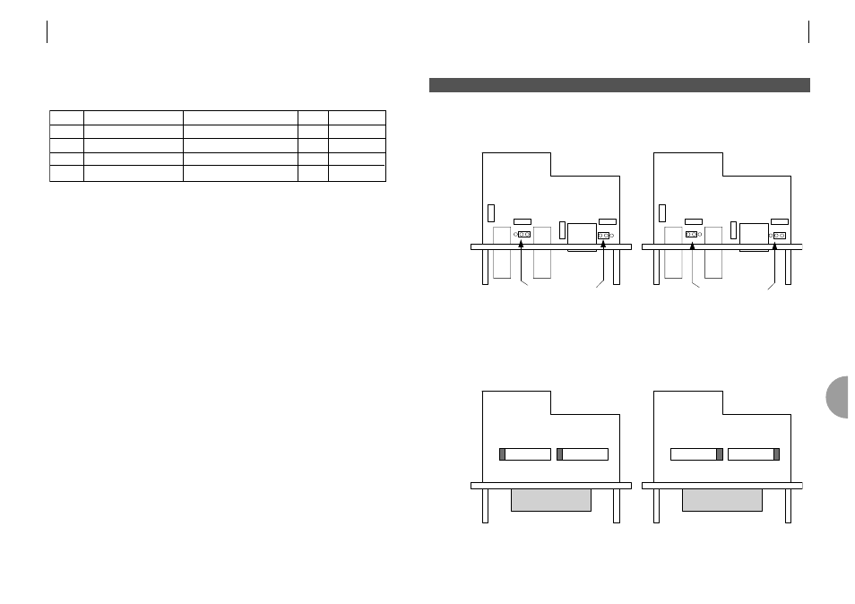
G.703 PLUG IN MODULE
The following diagrams show the location of the internal hardware links.
In all cases the factory default setting is shown on the left.
The 75ž G.703 receiver and the 120ž cable screen may be optionally connected directly to
ground or to ground via a capacitor. The fuses FS1 to FS4 are used to protect the circuit
against the transverse application of mains.
8.2
X.21 PLUG IN MODULE
The X.21 module may be configured as a DCE or DTE. The 120 termination is always in.
DCE
DCE
DTE
DTE
FS1
FS4
FS2
FS3
FS1
FS4
FS2
FS3
Cap to Ground
Direct to Ground
8
I N T E R N A L L I N K S A N D F U S E S
ATL TELECOM USER GUIDE
AM2048A
45
8
44
ATL TELECOM USER GUIDE
AM2048A
7.6.2
Indicators
There are four tri-colour LEDs that provide status information. These are interpreted as follows:
The single colour LED indicators are interpreted as follows:
Master (Green)
When lit, this LED indicates that the unit has been configured to operate as a ‘master’. The
default setting is for the unit to be a ‘slave’ in which case the LED will be turned off.
Test (Red)
This will be illuminated whenever:
the unit has a loop locally or remotely applied.
the unit is applying a remote loop.
the unit is running a data test.
LED Red
Amber Green
Off
Status
Urgent System Alarm(s) on Non-Urgent System Alarm(s) on OK
Power Off
Line 1
Loss Of Sync
High BER
OK
Not Applicable
Line 2
Loss Of Sync
High BER
OK
Not in use
Userport Urgent Userport Alarm on Non-Urgent Alarm on e.g. AIS
OK
Not Applicable