Lingenfelter L650100206 PP C6 Z06 Corvette Air Intake Instructions v3.02 small User Manual
Page 4
To remove the radiator shroud you need to temporarily disconnect and remove the engine oil cooler.
• Remove the left wheel house extension and left brake cooler
duct. To do this you will need to remove the three 7 mm
head screws from underneath the vehicle, remove the five T-
15 Torx head screws along the vertical wall of the wheel well
and remove the three push fasteners in the wheel well.
• Install oil drain pan under vehicle.
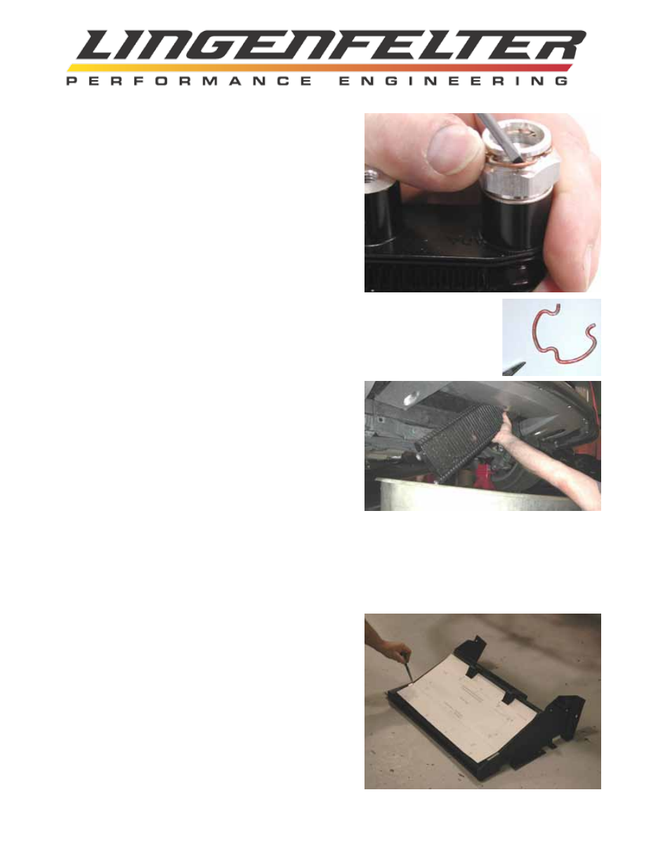
• Using a small pick tool, carefully remove the two retaining
clips holding the oil lines to the oil cooler. Do NOT pull the
oil lines from the cooler at this time. The pictures show the
clips and the fittings on the oil cooler. The oil cooler is shown
removed from the vehicle to make it easier to see the parts
involved.
• Using a 13 mm socket, remove the four screws retaining
the oil cooler. Allow the right side of the cooler to drop (see
picture).
• Disengage both oil lines and remove the oil cooler from the vehicle. Keep the ports aimed
upright to prevent additional oil spills. Be sure to reinstall the oil line retaining clips on
the oil cooler so that you don’t loose them. When you reinstall the oil lines later on, you
will not need to remove these clips - the lines simply push on.
• Cover the oil cooler ports and the oil lines to avoid contamination.
Remove the two plastic push pins holding the radiator shroud
to the bumper beam. Remove two plastic retainers from each
side of the radiator shroud.
Guide the side wings of the radiator shroud around the lower
brackets. Remove the shroud from the top side, pushing
condenser rearward as necessary for clearance. If the shroud
does not clear the bumper during removal, it may be easier to
free it from the under side of the vehicle.
NOTE: If you do not feel comfortable with performing the
modifications to your shroud that are listed in the following steps or you would prefer to keep the existing shroud
in stock form, LPE offers an already modified production GM shroud. Contact LPE or your LPE distributor.
Cut out the template, cutting along the outer short dashed line only. Thoroughly clean the shroud to ensure
adhesion of tape for the next step. Place the cut template on the shroud as shown, ensuring the line on the
template matches up with the crease on the shroud.
Secure the template in several places with tape. Use a cen-
ter punch to mark the centers of the holes to be drilled. You
should have 19 center punch marks. It is important to not
remove the template until all 19 holes are marked.
•
Remove template.
•
Drill four 5/16” holes first as shown on template.
•
Drill seven 11/32” holes as shown on template.
•
Drill eight 1/2” holes as shown on template.
•
Using a ruler & marking tool, connect outer edges of 1/2”
holes to form cut line as shown with “dashed lines” on tem-
plate.
•
Using saw or other suitable cutting tool cut on line drawn,
making sure to NOT CUT OUTSIDE OF LINE.
Page 3 of 8