Industrial Data Systems IDS 410 User Manual
Page 57
IDS 410/422 User's Manual
56
HARDWARE INSTALLATION AND WIRING
This section describes installation and wiring information for the interface ports. There are two
bi-directional serial ports, digital port with 3 TTL inputs, 3 TTL outputs, and one load cell input
port. The serial ports are used to interface to a printer and to a host device or PC for continuous
output. The TTL outputs and inputs are used for remote switch input and relay control. The load
cell input is used to interface to the scale platform.
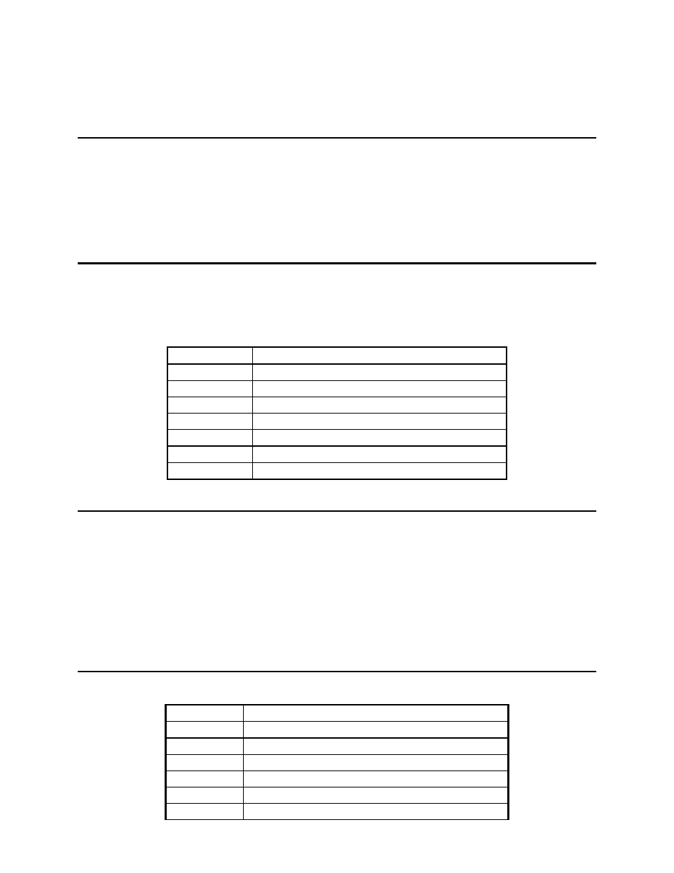
Load Cell Connector – TB1
NOTE: Remove jumpers JP1 and JP2 to enable SENSE LINES for 6 wire load cells. Wire the
sheilding from the load cells to the chassis not TB1 pin 7.
Load Cell Terminal Block – TB1
Pin #
Signal Name
1
+ Signal
2
- Signal
3
+ Excitation
4
+ Sense
5
- Sense
6
- Excitation
7
Analog ground
(NOT FOR SHIELD)
Power Source AC / DC
The unit come standard with an onboard transformer the AC interface connector is a 3 pin
Molex type, this connects to the motherboard where the 3 pin Molex header is mounted
on the board marked A/C power.
For DC power applications there ia a 2 position terminal block marked PWR-DC.
Note the polarity of the terminals the positive is marked as ( + ) the negative ( - ).
The DC power input will exept +12 to +28 VDC. Remove AC power before wiring
for DC.
I/O Port Connector - TB 3
The I/O port connector has Com Ports 1 and 2 and the digital TTL inputs.
Pin #
Signal Name
1
+5V (TX- 20 mA CL)
2
TXD 1 (RS232)
3
RXD1 (RS232)
4
Soft +5 volts (220 ohm to +5V)
5
GND
6
CL TX +