Manual mode configuration c p n – Aviom MH10f User Manual
Page 32
25
mH10 c
oNFigurAtioNs
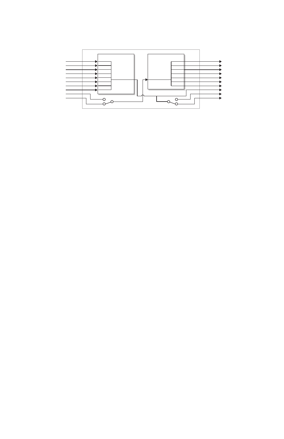
A-Net Receive
(Ports 1-10)
A-Net Transmit
(Ports 1-10)
A-Net Receive
(Ports 1-10)
A-Net Transmit
(Ports 1-10)
A-Net Receive
(Ports 1-10)
A-Net Transmit
(Ports 1-10)
1
2
3
4
5
6
7
8
9
10
1
2
3
4
5
6
7
8
9
10
Merger
Distributor
1
2
3
4
5
6
7
8
9
10
1
2
3
4
5
6
7
8
9
10
Merger
Distributor
1
2
3
4
5
6
7
8
9
10
1
2
3
4
5
6
7
8
9
10
Merger
Distributor
Manual Mode Configuration C
P
N
ote
: When using Configuration C in Manual Mode, be sure that both
MH10/MH10f Merger Hubs are set to Configuration C to avoid
creating a data loop.
Configuration C Example
This example shows a stage‑to‑FOH application with a monitor console, a
64‑channel recording split, and a broadcast feed from the front‑of‑house
mix outputs. Two MH10 Merger Hubs are shown; MH10f hubs can be
substituted.
Inputs on the stage (mic, line‑level, or digital) are connected to ports 1‑8 of
the MH10/MH10f on stage. Port 8 on this MH10/MH10f is connected to output
modules that feed the monitor console and recording devices. (Optionally,
another MH10 or MH10f could be connected to port 8 to create a parallel
rather than serial digital split.)
Digital audio from the stage inputs is merged and then transmitted via port
10 to the second MH10/MH10f at the front‑of‑house mixing position. (Port 9
is the redundant Cat‑5e or fiber backup cable, shown with a dotted line in
the diagram that follows.)
At FOH, port 10 is connected to four output modules which feed the front‑
of‑house mixing console. The engineer creates mix content and sends it
into an input module (marked as “Returns 1‑16”) at port 5 in the diagram.
Port 8 on the front‑of‑house MH10/MH10f is also connected to an output
module located in the broadcast area. This module outputs the same FOH
mix content.