Figure 3-11: pump fittings – Hale ESP Priming System User Manual
Page 31
31
ESP Primer System Instruction Guide
p/n: 029-0810-01-0
In sta llatio n
❑
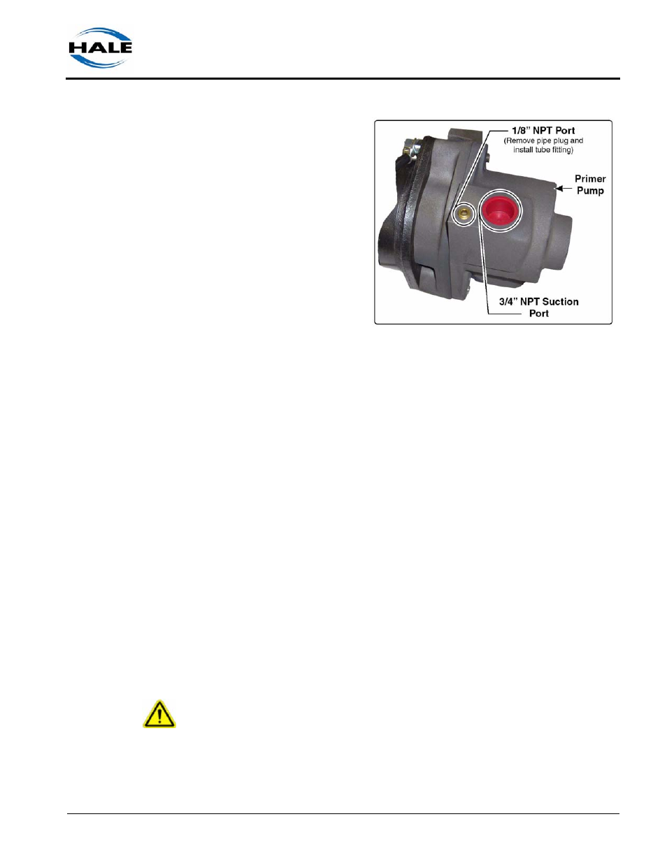
2.
Remove the 1/8” NPT
pipe plug in the top of
the primer pump and
install one 1/8” NPT x
5/16” (8 mm) tube fit-
ting. (See Figure 3-11:
“Pump Fittings.”) Use
appropriate thread
sealant.
Note: If the tank is installed
above the primer pump and
is not a Hale tank, the fitting
installed in the top of the
lubricant tank must contain
a vent hole (#60 drill,) in the
top of the fitting to create a
vacuum break (break the
siphon and stop the flow of lubricant when priming stops).
3.
Run DOT air brake tubing (5/16” /8 mm) from the lubricant storage tank
to the primer pump fitting and secure the tubing (tubing clamps). (See
Figure 3-10: “Typical ESP Lubricated Primer Layout,” on page 30.)
4.
Install a separate discharge collection container (tank), three (3) gallons
(11 liters) MINIMUM, to collect all discharged fluid during priming in
accordance with your departmental and/or local environmental regula-
tions.
5.
Connect a hose (2-1/2” / 64 mm) from the primer pump discharge to a
separate discharge collection container. Clamp hose using appropriate
hose clamps.
6.
Install a tank vent, 1-1/2” (38 mm) MINIMUM at the top of the discharge
tank. (See Figure 3-10: “Typical ESP Lubricated Primer Layout,” on
page 30.)
7.
Install a drain valve in the discharge tank to enable easy fluid drainage
and disposal, in accordance with your departmental and/or local envi-
ronmental regulations.
WARNING !
DO NOT ALLOW COOLANT TO DISCHARGE TO THE GROUND. REVIEW
YOUR DEPARTMENTAL AND/OR LOCAL ENVIRONMENTAL REGULATIONS
REGARDING THE USE OF AND DISPOSAL OF PROPYLENE GYLCOL
COOLANTS.
Figure 3-11: Pump Fittings