Figure 3-9, Pvg panel placard and valve plumbing layout – Hale ESP Priming System User Manual
Page 28
❑ Installation
28
ESP Primer System Instruction Guide
p/n: 029-0810-01-0
3.
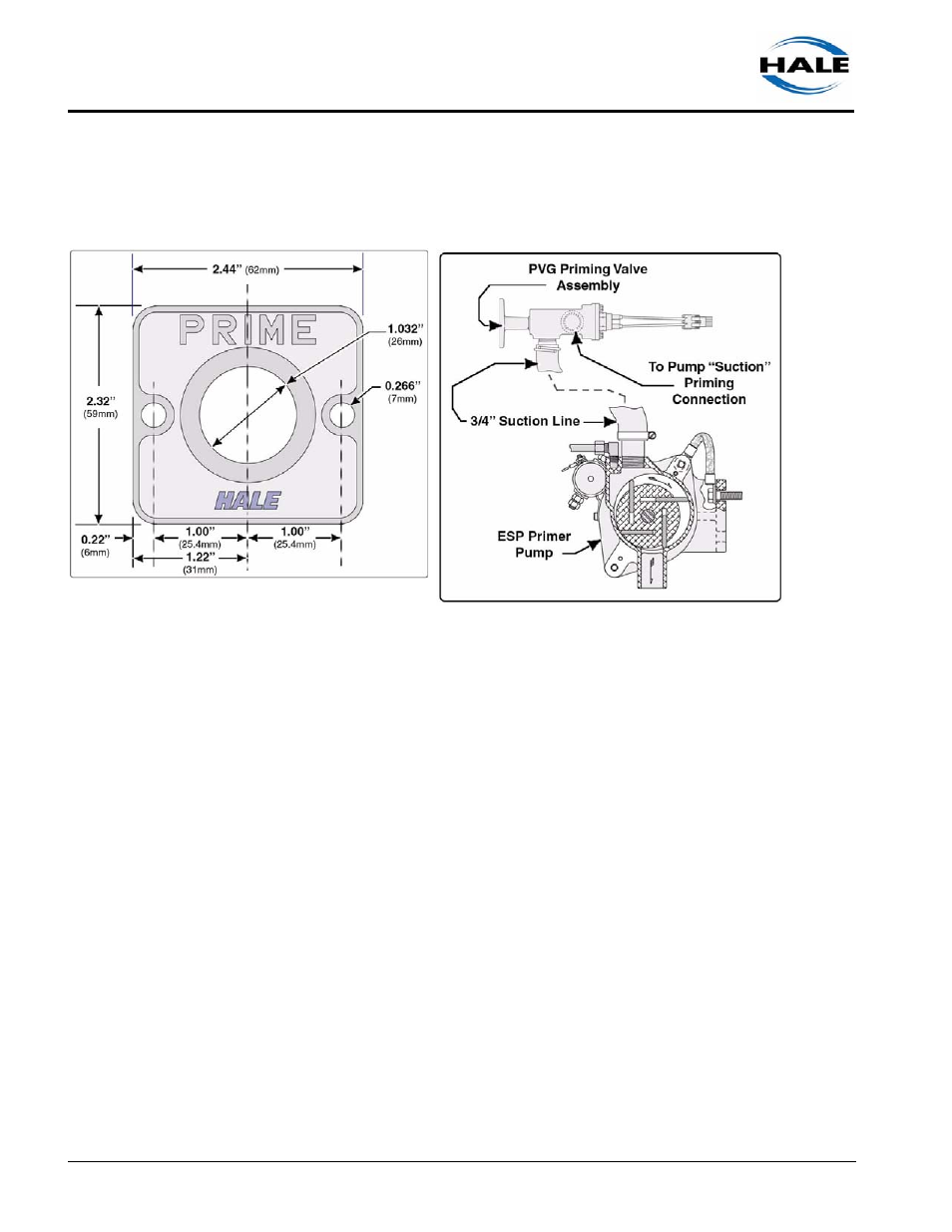
Drill or punch one 1.032” (26 mm) and two 0.266” (7 mm) diameter
holes in the panel. (See Figure 3-9: “PVG Panel Placard and Valve
Plumbing Layout.”)
Figure 3-9: PVG Panel Placard and Valve Plumbing Layout
4.
Install the PVG panel placard and valve body to the operator’s panel.
(See Figure 3-9: “PVG Panel Placard and Valve Plumbing Layout.”)
5.
Secure the assembly with two (2) 1/4”-20 screws. Apply a drop of Loc-
tite #246 to each screw.
6.
Install the setscrew, with allen head facing out, into the valve body stem
until the setscrew bottoms-out. Apply a drop of Loctite #246 to the set-
screw threads.
7.
Install the handle and washer to the valve stud setscrew. Apply a drop
of Loctite #246 to the setscrew threads to assure the handle does not
work loose from use.
8.
Install a 3/4” NPT hoes fitting into the PVG valve and connect appropri-
ate 3/4” ID hose between the valve and the primer pump.
9.
Install another 3/4” NPT x 1/2” compression hose fitting, rated at 250
PSI minimum, into the side of the PVG valve and connect hose between
the valve and the suction side of the pump. (See Figure 3-9: “PVG
Panel Placard and Valve Plumbing Layout.”)