❑ Installation
20
ESP Primer System Instruction Guide
p/n: 029-0810-01-0
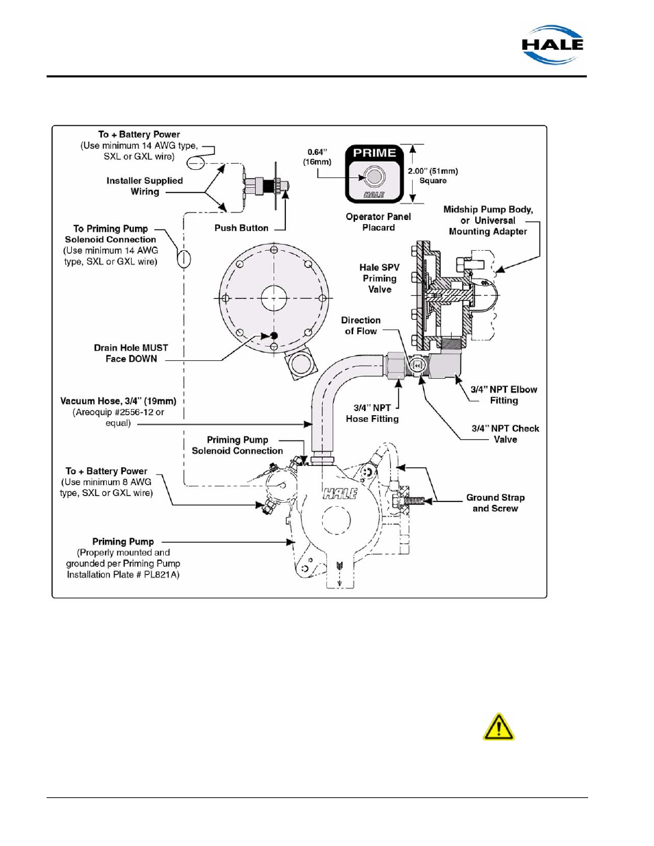
Figure 3-2: Typical Hale SPV Typical System Layout
SPV Placard and Pushbutton
WARNING !
DISCONNECT OR TURN OFF THE MASTER BATTERY SWITCH PRIOR TO
SERVICING THE HALE SPV ELECTRICAL COMPONENTS.