Installation – InnoMax Adjustable Bed Base User Manual
Page 14
PowerBASE™ Owners Manual 99300787-i
14
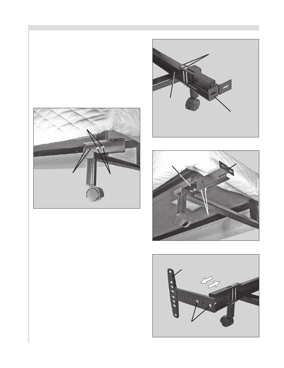
fiGure 20: Bed base Type B channel connector attachment.
fiGure 21: Bed base Type a bracket channel attachment.
fiGure 23: Bed base Type a headboard bracket flange
attachment.
fiGure 22: Bed base Type B bracket channel attachment.
insTallaTiOn
d. Position channel connector so that
the flat side is flush against bed base
frame. Attach channel connector to
bed base frame using (2) 1½ inch
long hex head bolts/nuts (
FIGurE
20). Tighten bolts. Note: For beds
with 74” base length, use inner
mounting holes. For beds with 80”
base length, use outer mounting
holes (FIGurES 18 and 20).
80” Base
lenGTH
MOunTinG
HOles
use (2) 1½ inCH lOnG HeX Head
BOlTs and nuTs (TiGHTen) TO
aTTaCH CHannel COnneCTOr
TO Bed Base fraMe
74” Base
lenGTH
MOunTinG
HOles
adjusTaBle
Bed Type B
e. Using (2) 3 inch long carriage bolts/
nuts, attach (1) headboard bracket
channel to bed base frame (bed base
Type A) (
FIGurE 21) or (1) channel
connector (bed base Type B) (
FIGurE
22). Hand tighten bolts/nuts (loosely)
to allow adjustment of the headboard
bracket channels.
f. Attach (1) headboard bracket flange
to one of the bracket channels with
(2) 1 inch long hex head bolts/nuts
(
FIGurES 23 and 24). Tighten bolts.
g. Repeat procedure to attach the other
headboard bracket.
adjusTaBle
Bed Type a
Bed Base
fraMe
BraCkeT
CHannel
use (2) 3 inCH lOnG CarriaGe
BOlTs TO aTTaCH BraCkeT
CHannel TO Bed Base fraMe
adjusTaBle
Bed Type B
adjusTaBle
Bed Type a
SLIDE BRA
CKET
ASSEMBLIES IN OR
OUT T
O A
CHIEVE
POSITION
CHannel
COnneCTOr
BraCkeT
CHannel
HeadBOard
BraCkeT
flanGe
use (2) 3 inCH lOnG CarriaGe
BOlTs TO aTTaCH BraCkeT
CHannel TO Bed Base fraMe
use (2) 1 inCH lOnG HeX Head
BOlTs TO aTTaCH BraCkeT
flanGe TO BraCkeT CHannel