Figure 8, Figure 9, Figure 10 – Hellenbrand H200HF Series User Manual
Page 11
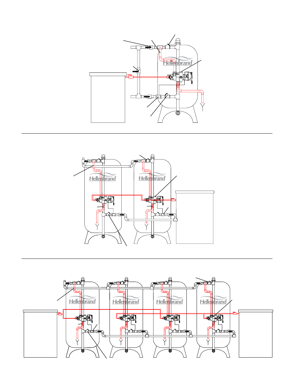
H200 HF Single Tank Installation
H200 HF Twin Alternating Installation
H200 HF Triplex/Fourplex Installation
Brine Tank
See NOTE Figure 7
Figure 8
See NOTE Figure 7
Figure 9
See NOTE Figure 7
Figure 10
Outlet
Meter
High Flow
Service Valve
1
Bypass Valve
Inlet
Outlet is
Plugged
High Flow
Service Valve
Pipe is on
an angle
Isolation Valve
1
Air or water operated
Brine Tank
Outlet
Inlet
Meter
DLFC
High Flow
Service Valve
Valve outlet is
plugged
DLFC
Pipe is on
an angle
High Flow
Service Valve
1
High Flow
Service Valve
1
Inlet
Pipe is on
an angle
Meter
DLFC
Outlet
High Flow
Service Valve
Valve outlet is
plugged
11
Brine Tank(s)
Brine Tank(s)
1
Air or water operated
1
Air or water operated