10 jumper settings, Umper, Ettings – IEI Integration PPC-37xx-N270 v2.00 User Manual
Page 54: Figure 4-15: jumper locations
PPC-37xx-N270 Panel PC
Page 40
Step 5:
Attach the CD drive bracket to the CD drive. To do this, align the four retention
screw holes in the CD drive bracket with the retention screw holes on the side of
the CD drive. Insert four retention screws into the bracket on both sides of the
HDD.
Step 6:
Install the CD drive into the PPC-3712 by aligning the retention screw holes in
the sides of the CD drive bracket with the retention screw holes on the left panel
and inside the chassis. Insert the three retention screws.
Step 7:
Connect the IDE ribbon cable and power cable from the connectors on the
motherboard to the rear of the CD drive.
Step 0:
4.10 Jumper Settings
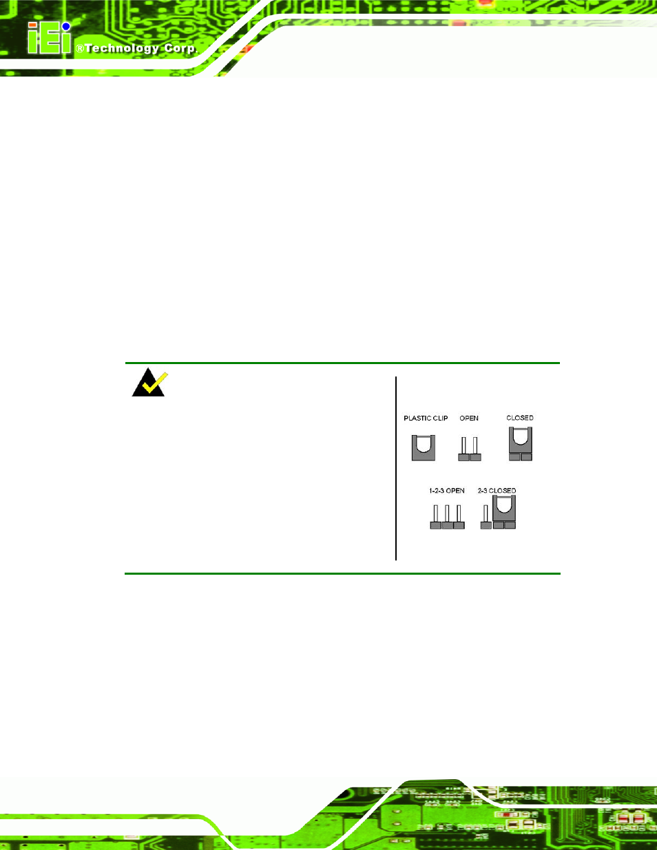
NOTE:
A jumper is a metal bridge used to close an
electrical circuit. It consists of two or three metal
pins and a small metal clip (often protected by a
plastic cover) that slides over the pins to connect
them. To CLOSE/SHORT a jumper means
connecting the pins of the jumper with the plastic
clip and to OPEN a jumper means removing the
plastic clip from a jumper.
Figure 4-15: Jumper Locations
The following jumpers can be found on the motherboard installed in the PPC-37xx-N270.
Before the PPC-37xx-N270 is installed, the jumpers must be set in accordance with the
desired configuration. The jumpers on the PPC-37xx-N270 motherboard are listed in
6
Table 4-1
.