Vf series, General pump – General Pump VF Repair Manual User Manual
Page 7
GENERAL PUMP
A member of the Interpump Group
VF SERIES
Page 7
A) Assembly / Disassembly of the crankshaft without replacing the bearings
After removing the side covers, as indicated in paragraph 2.1.2, check the rollers and their races for wear; if
all parts are in good condition, fully clean the components with a suitable degreaser and grease them again
evenly using the same oil in the crankcase. The same shims can be used again, being careful to fit them
under the cover on the site glass side. After installing the complete unit (sight glass side flange and engine
side flange), check that the shaft’s rolling torque - with the connecting rods free - is at least 3 Ft. Lbs. (4 Nm),
Max 5 Ft. Lbs. (7 Nm). To position the two side covers on the crankcase, initially use 3 M6 x 40 screws as
shown in fig. 6, and then the fastening screws. The shafts rolling torque (with connecting rods coupled must
not exceed 6 Ft. Lbs. (8 Nm).
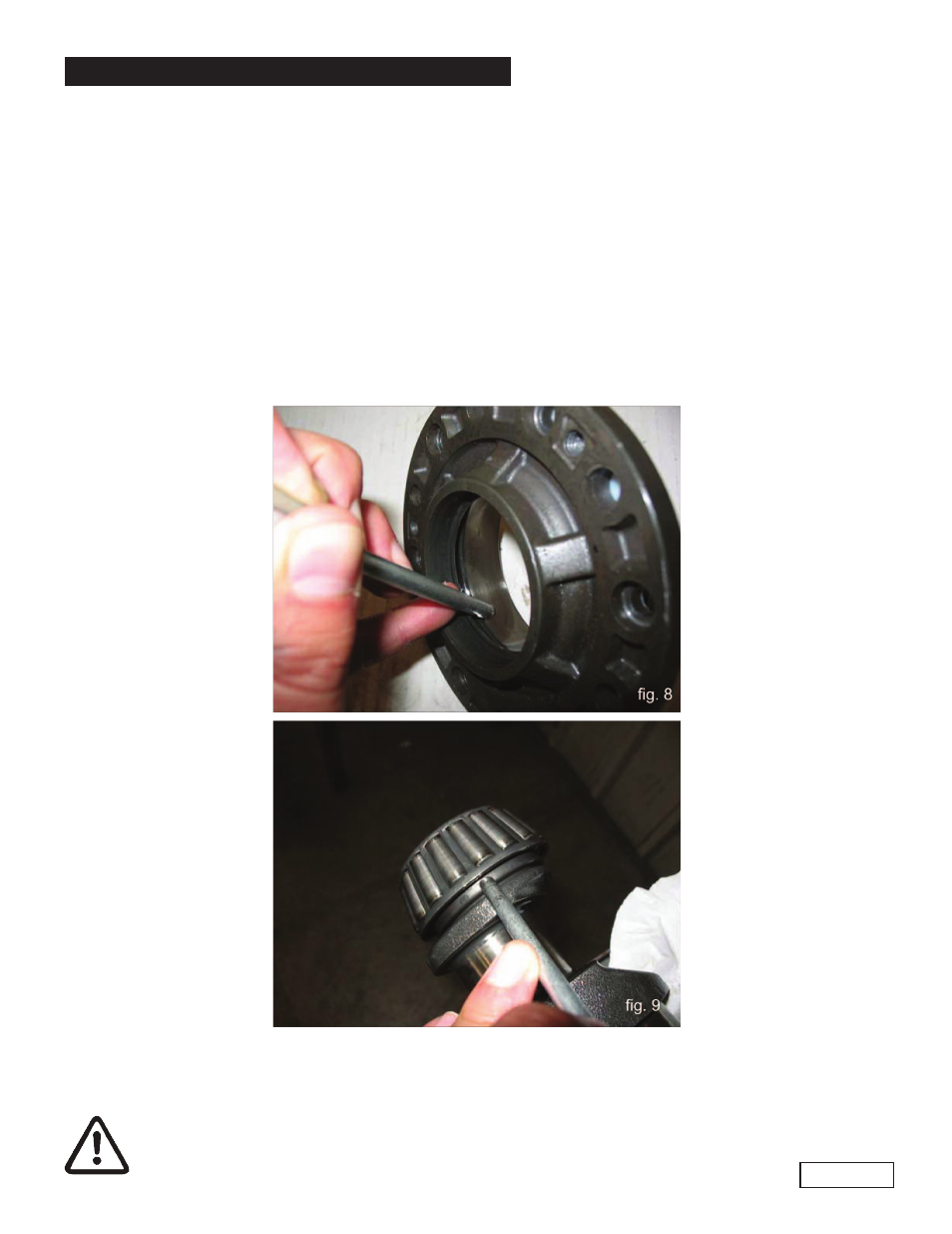
B) Disassembly / Assembly of the Crankshaft With Bearings Replacement
After disassembling the side covers as indicated in paragraph 2.1.2, remove the outer ring nut of the bearings
from their covers and the inner ring nut, with the remaining part of the bearing, from the two shaft extremities
using a standard pin extractor or similar tool as indicated in figures 8 and 9.
The new roller bearing can be mounted at room temperature with press; it is necessary to lay them on the
lateral side of the relevant ring nuts with opposite rings. The driving operation can be facilitated by heating
the relevant parts to a temperature ranging between 250
0
- 300
0
F, (120
0
- 150
0
C), making sure that the
ring nuts are correctly fitted in their seats.
Never invert the parts of the two bearings.