Vf series – General Pump VF Repair Manual User Manual
Page 12
F)
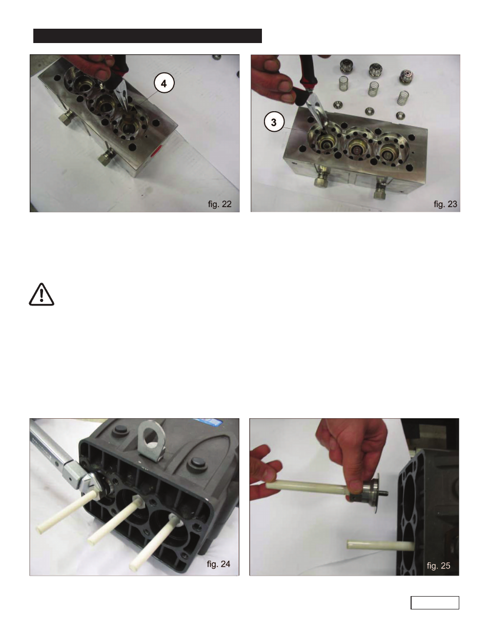
Extract the delivery pads, #3, and the related guides, #4, and springs as shown in fig. 22-23;
check for wear and replace components as necessary.
2.2.2 Assembly of the Head - Liners - Valves
To reassemble the components, invert the previously listed operations, paying attention to the correct
assembly of the liner manifold; when the component is mounted, the two rough casting exhausts
present on one of the sides must be oriented towards the lower part of the crankcase (pump bracket
side). Heads - Liners: proceed with assembly and head screw calibration, and then continue
with the calibration of the liner fastening screws. For fastening torque values, please follow the
recommendations in paragraph 3.
2.2.3 Disassembly of the Plunger Unit - Supports - Seals
The plunger unit does not require periodic maintenance. Service operations are limited to the visual
inspection of the cooling circuit’s draining. In case of anomalies/oscillations on the delivery pressure gauge,
or pulsating of the cooling circuit’s draining pipe (if flexible), seal packings must be inspected and replaced
if necessary. To extract the plunger unit operate as follows:
A)
Separate the head and the liner manifold from the pump crankcase as indicated in paragraph
2.2.1, point C (fig. 15-16).
GENERAL PUMP
A member of the Interpump Group
VF SERIES
B)
Remove the pumping assembly with a fork wrench and check for wear as indicated
in fig. 24-25; replace if necessary.
Page 12