Vf series – General Pump VF Repair Manual User Manual
Page 10
GENERAL PUMP
A member of the Interpump Group
VF SERIES
C)
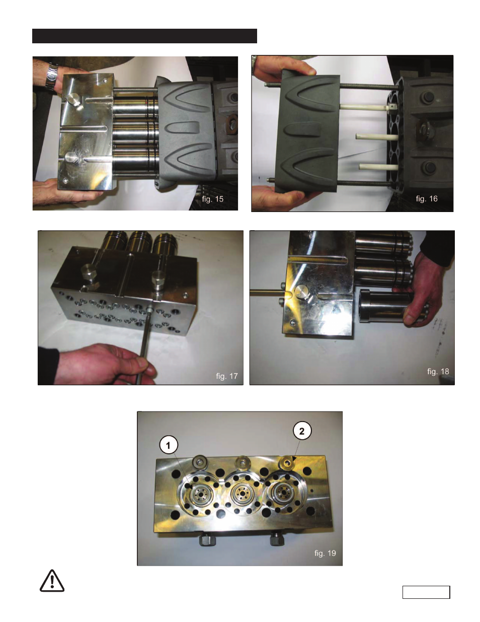
Separate the head and the liner manifold from the pump crankcase as shown in fig 15-16.
D)
Remove the M8 x 100 screws that fasten the liners to the head as shown in fig. 17 and
proceed as indicated in fig. 18.
When disassembling the liners, be careful not to lose the valve seats #1 and the flat valves #2
as shown in fig. 19; in fact, they may fall since they are only laid down.
Page 10
See also other documents in the category General Pump Hardware:
- 47 Series (4 pages)
- 60 TC Series (4 pages)
- 66 Series HTF, TSF & TSP Crankshaft Flip (4 pages)
- 66 Series TSF (4 pages)
- 66 Series TSP (5 pages)
- 71 Series Gearbox (13 pages)
- HE (20 pages)
- HF Owner Manual (24 pages)
- HF Repair Manual (17 pages)
- HTCK3623S (19 pages)
- HTCK4050S (19 pages)
- KE Owner Manual (22 pages)
- KE Repair Manual (16 pages)
- KEZ Owner Manual v.1 (17 pages)
- KEZ Owner Manual v.2 (17 pages)
- KEZ Repair Manual (16 pages)
- KFM Owner Manual (17 pages)
- KFM Repair Manual (16 pages)
- KF Owner Manual (22 pages)
- KF Repair Manual (15 pages)
- KFZ Owner Manual (24 pages)
- KFZ Repair Manual (15 pages)
- KL (19 pages)
- KS Owner Manual (23 pages)
- KS Repair Manual (21 pages)
- T16A-18A-20A-22A (21 pages)
- T24A-26A-28A-30A-26A-40A (22 pages)
- KT (35 pages)
- LH (21 pages)
- LK Owner Manual (24 pages)
- LK Repair Manual (50 pages)
- MH (18 pages)
- MK Owner Manual (21 pages)
- MK Repair Manual (45 pages)
- MKS Owner Manual (21 pages)
- MKS Repair Manual (45 pages)
- MS Owner Manual (20 pages)
- MS Hydraulic Drive Owner Manual (2 pages)
- MSS Owner Manual (21 pages)
- MW Owners Manual (34 pages)
- MW Repair Manual (54 pages)
- Pump Installation and Service Manual (12 pages)
- SH (18 pages)
- SK Owner Manual (22 pages)
- SK Repair Manual (44 pages)