Perma Pure GASS-2040 User Manual
Page 23
23
GASS-2040 User Manual | Original Instructions
Dual element dryer
a. Thread the tool into one of the ports from which the plugs were just removed and tighten by
hand. Turn the handle until resistance is felt. Then slowly turn the handle 2-3 turns. The
coupling fitting will begin to move away from the shell tubes.
b. Remove the tool and thread it into the other port on the same coupling fitting and tighten by
hand. Slowly turn the handle 2-3 turns.
c. Repeat steps a-b until the coupling fitting is free of the shell tubes.
d. Repeat steps a-c for the other coupling fitting.
e. At this point, the dryer element/shells should be free of the coupling.
f. Remove an o-ring (item 8) from one of the membrane element headers and slip the ele-
ment from the opposite end of the shell tube.
g. Repeat step f for the other membrane element/shell tube assembly.
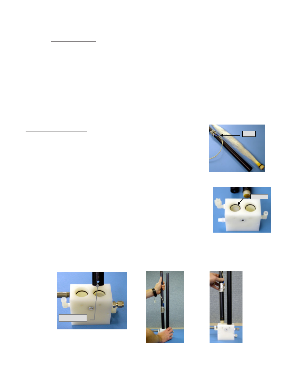
2. PD Dryer Reassembly
1. Insert a membrane element into the heated shell tube and install
o-rings (item 8) into the grooves on each header (See Figure 15).
The membrane element should now be constrained to the shell by
the o-rings.
2. If this is a dual membrane element dryer, repeat step 1 for the other
membrane element/shell tube assembly.
3. Perform the following steps to complete the reassembly:
a. Locate one of the coupling fittings and place it on a hard
surface with the shell tube bores facing up. Install o-rings (item
6) in the grooves (See Figure 16).
b. Skip this step for dual element dryers. For a single element
dryer: Insert the end of the empty shell into the bore of the
coupling fitting that has the header plug residing in it.
(Important! - Position the purge air holes as shown on the
drawing). Press the assembly into place in the coupling fitting.
(See Figure 17)
c. Insert the shell/element assembly into the other bore and press
into
place. (Important! - Position the purge air holes as shown on the drawing. Repeat for
the second shell/element assembly (See Figure 18-19).
Figure 15
Heater
Header plug
Figure 16
Purge air holes
Figure 17
Figure 18
Figure 19