Gass-2040 user manual | original instructions – Perma Pure GASS-2040 User Manual
Page 11
11
GASS-2040 User Manual | Original Instructions
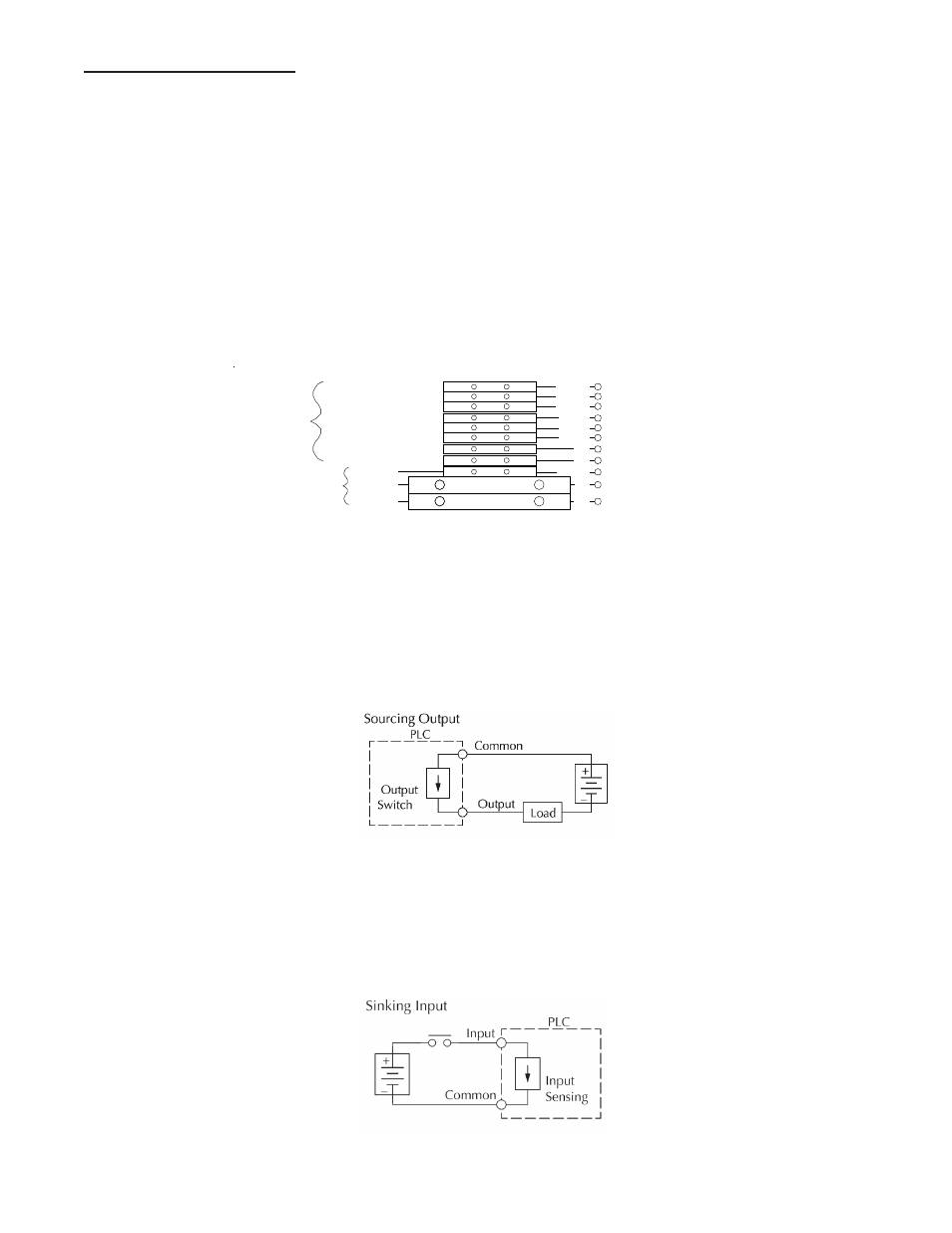
Figure 5
3.2 Electrical Connection
a. Power Wiring
The GASS-2040 system is intended to be hard wired via a customer supplied disconnect switch
and wire capable of supplying 5A/10A at 115/230/VAC. The external disconnect switch must meet
IEC 60947-1 & 60947-3 stds and must be installed in close proximity to the equipment, within easy
reach of the operator and shall be clearly marked as the disconnecting device for the GS-2040.
Connect the system to an appropriate earth ground. Adhere to all electrical code requirements in
effect at the installation site.
Connect the power wiring as shown in Figure 4 below. The fuse block is supplied with 1.25" x 0.25"
glass fuses and if necessary should be replaced with one of similar rating. A fuse block for PLC
power, located in the upper terminal strip, is supplied with a 5mm x 20mm, 1.0A, fast-blow fuse and
should be re-
placed with one of
similar rating,
if necessary.
Figure 4
b. I/O Wiring
The PLC outputs operate at 24 VDC and are “sourcing” (See Figure 5). This means that when
commanded to turn on by the PLC logic, the output terminal goes from 0 VDC to +24 VDC and
supplies current to the device being signaled or powered. The device must pull no more than 0.5A
and must have a minimum load of 10 mA at 24 VDC. A 0 VDC terminal connection is supplied as a
current sink to complete the output circuit.
The PLC inputs operate at 24 VDC and are “sinking” (See Figure 6). This means that the input is to
turn on and signal the PLC logic that an event has occurred or is desired, +24 VDC must be
applied to the input terminal. A +24 VDC terminal is supplied as a current source to complete the
input circuit.
Figure 6
TB-C011
TB-C012
TB-C013
TB-C24V
FUSE BLOCK, F2
TO PLC TERM. Y11
TO PLC TERM. Y12
TO PLC TERM. Y13
TO TB-0V
TB-C0V
TB-G
TB-C102
TB-C101
TO PLC TERM. X1
TO PLC TERM. X2
TO TB-24V
TO POWER BUTTON (14 AWG)
TO TB-G (14 AWG)
TO TB-AC(N) (14 AWG)
POWER
BLK
RED
WHT, X2
GRN/YEL
BLU
BRN
WHT, X1
GRY, Y13
GRY, Y12
GRY, Y11
CUSTOMER
NEUTRAL, L2
GROUND
CONNECTIONS
CUSTOMER I/O
CONNECTIONS
MAN. FILTER DRAIN
MAN. FILTER BB
GEN. LOW TEMP ALARM
LOW PURGE AIR FLOW ALARM
GENERAL ALARM
0 VOLTS DC
24 VOLTS DC
POWER
CUSTOMER
LINE, L1
GROUND
MAN. FILTER DRAIN
MAN. FILTER BB
GEN. LOW TEMP ALARM
LOW PURGE AIR FLOW ALARM
GENERAL ALARM
0 VOLTS DC
24 VOLTS DC
TB-C104
TO PLC TERM. X4
WHT, X4
REMOTE PUMP SHUT-OFF
FUSE BLOCK, F1