Voltage drop test, Regulator charging voltage, Alternator output test – GxT V040-01, Battery Tester User Manual
Page 6
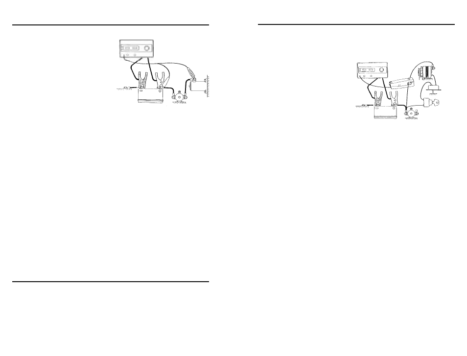
VOLTAGE DROP TEST
The voltage drop test is a very helpful diagnostic test for deter-
mining the condition of cables
and connections for the starting
charging circuit. The voltage drop
test can be used on any part of
the circuit. In the example below,
we are checking the entire circuit
from the positive side of the bat-
tery to the starter.
1. Be sure the Load Knob is
turned to OFF before con-
necting the analyzer cables to the battery. Take note of the
safety precautions on the back cover of this manual.
2. Connect the analyzer Battery Clamps to the battery termi-
nals; Red to positive, Black to negative.
3. Select external volts.
4. Connect the external volts leads as shown in the illustration.
Connect the Red auxiliary lead to the positive side of the
battery. Connect the Black lead to the input terminal of the
starter.
5. Disable ignition to prevent the engine from starting during the
test.
4. Operate the Starter and read the voltmeter while cranking.
5. Test Conclusions. Good circuits drop less than 0.50 volts on
a 12 volt system. Typically you should not have more than
0.10 volts drop per connection.
BATTERY
RED
BLACK
STARTER
SOLENOID
RELAY
CHASSIS
Connections For
INSULATED - POS CURCUIT TEST
POS
REGULATOR CHARGING VOLTAGE
Follow the same setup and test procedure used for the alterna-
tor test, except put the Amp Probe around either battery cable.
Once the charging amperage drops below 20 amps, the voltage
displayed will be the regulator setting. This should be between
13.5 and 15.5 volts on a 12 volt system.
BATTERY
ALTERNATOR
OUT
FIELD
REGULATOR
KEY SWITCH
CHASSIS
Connections For
AMPERAGE OUTPUT TEST
ALTERNATOR OUTPUT TEST
Always compare test results with manufacturer’s specifications
before coming to conclusions regarding the performance or ef-
ficiency of charging systems and their components
1. Be sure the Load Knob is
turned to OFF before con-
necting the analyzer cables
to the battery. Take note
of the safety precautions
on the back cover of this
manual.
2. Connect the analyzer Bat-
tery Clamps to the battery
terminals; Red to positive, Black to negative.
3. With the Amp Probe jaws closed and not around any wires,
press the Zero Amps buttons until the Amps Display shows
“000”
4. Place the Amp Probe around the alternator output wire. Try
to position the probe away from strong magnetism near the
back shaft end of the alternator to avoid measurement error.
5. Display Battery Volts.
6. Start and run the engine at about 2000 RPM.
7. Turn the Load ON and increase until the battery voltage
decreases to be between 12 and 13 volts while reading the
output amperage.
8. Turn Load OFF and reduce RPM.
9. Test Conclusions
a. If the Amps Ripple lamp stayed on during the output test
replace the alternator.
b. If the amperage abruptly decreased during the test check
for a loose belt.
c. If output was less than 90% of rating use the voltage drop
test to check output resistance.
d. If output did not change, full field the alternator. If the
alternator output increases, replace the regulator.