Introduction, Installation, 1 assembly – GeneralAire GFX50 User Manual
Page 4: 2 dimensions
1. INTRODUCTION
The GFX50 includes Indoor and Outdoor Temperature Sensors, Indoor Humidity Sensor and Control Unit.
2. INSTALLATION
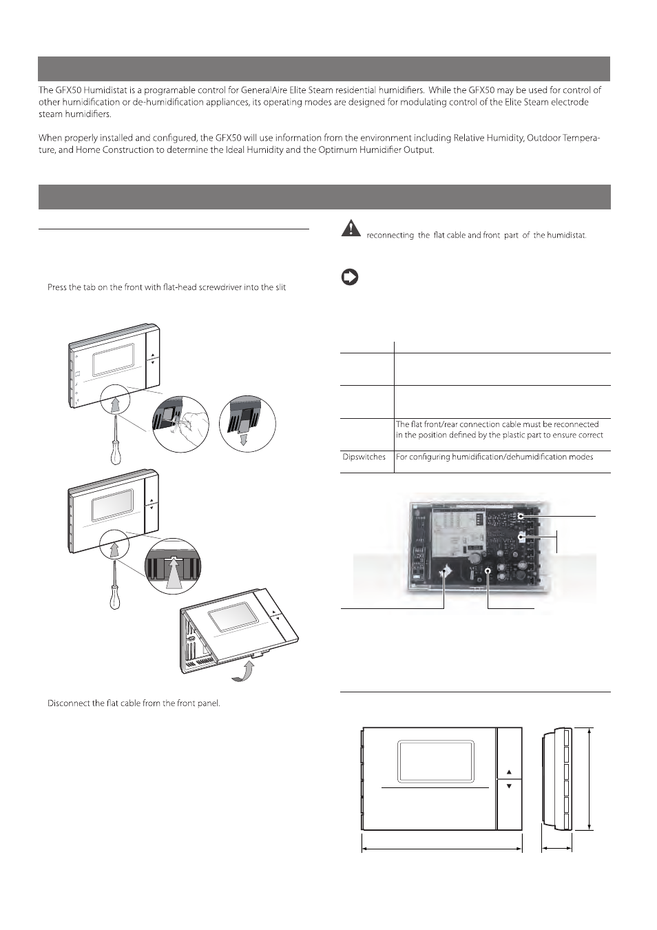
2.1 Assembly
Open the product by detaching the front from the mounting base, as
shown in Fig. 2.a:
Remove the locking tab and screw from the the base underside.
•
Slide the plastic tab back as shown to remove it from the base.
•
•
upwards.
in the middle on the bottom of the case while lifting the front panel
clock
set
mode
an
h ld
resume
aria
cloc
k
set
mode
fan
hold
resume
Fig. 2.a
•
Fasten the humidistat base to the wall using the screws supplied.
•
Access the terminal block by squeezing the clips on the terminal cover.
•
•
Important:
Make sure all connections are complete before
Note:
For the purposes of electrical safety (EN60730-1), once the
controller has been installed, replace the plastic locking tab in the
humidistat base.
Accessories and dipswitches (Fig. 2.b)
Connector
Function
J1
- Supervisor serial connection using code IROPZ48500.
- Key connector for copying the parameters. The serial
connection, if used, must be momentarily disconnected..
J2
Not Used.
FLAT
Front-rear
polarity
Tab. 2.a
J2 = sonda esterna T+H - ADCF006500
J1 per opzione
seriale o chiave
di programmazione
FLAT Front-Rear
Dip-switches
Fig. 2.b
2.2 Dimensions
For installation, see the drilling template included in the packaging.
5 5/16” (135mm)
1 7/16” (36mm)
3 3/8”
(86mm)
Fig. 2.c
4
Make the necessary connections and run the wires through the hole
in the middle of the base. Separate the sensor wires from the control
wires. The diagrams are shown in Section 2.3.