GeneralAire HC-201 User Manual
Hc-201, Duct high limit humidistat, Application
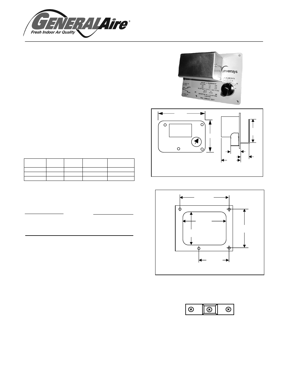
HC-201
Duct High Limit Humidistat
Application
For low or line voltage on-off control of humidifiers,
dehumidifiers, valves, solenoids valve compressors, relays, etc.
Specifications
Control Dial Settings: 15 to 95% RH.
Humidity Sensing Element: Nylon ribbon.
Differential: 5% RH.
Environment:
Ambient Temperature Limits,
Shipping & Storage -40 to 140
O
F
Operating 40 to 125
O
F
Humidity, 5 to 95% RH, non-condensing.
Location, NEMA 1, indoor locations only.
Electrical Switch: Snap-acting SPDT (see Fig. 1)
Ratings, (See Table 1)
Connections: Coded screw terminals.
Cover: Metal.
Mounting: The outside surface of the return air duct.
Dimensions: 4 ¾” X 6 ½” X 3 ½” (see Fig.2)
Ta ble 1. Maximum Electrical Ratings
AC V olt
50/60 Hz
FLA
LRA
Resistive
Amps
Pilot Dudy
VA
24
-
-
8
60
120
7.2
43.2
8
345
240
3.6
21.6
8
345
Mounting
Mount the H C -20 1 on the outside surface of the return air duct in
a horzontal position where it is exposed to freely circulating air.
CAUTION!
Avoid locations where excessive moisture, corrosive fumes,
vibration or high ambient temperatures are present .
T ypical Installation
1.
2.
Drill the four mounting holes as indicated on Figure 2.
using a 1/8” drill.
3.
Cut out center portion of ducts outlined on template.
4.
Using four (4 ) mounting screws, mount
humidistat to the duct.
5.
Remove the cover and make all electrical connections
in accordance with job wiring diagram and in
compliance w ith nation and local electrical codes (see Fig.3).
6.
Replace the cover.
Turn dial knob to desired setting. If locked dial setting
is desired, remove dial knob, tighten the dial lock
screw and replace knob.
5 1/2”
5 15 /16”
3 3/4”
4 1/4”
4 3/16”
Figure 2. Template Dimensions
6 1/2
4 3/4
Front View
Side View
Figure 1 HC -201 Dimensions
2 1/4
3/4
1 1/4
2 13 /16
Dimensions in inches
Micro Switch Terminals
Figure 3. Connect Humidifier To
“ORN” And “BRN” Terminals.
ORN
BRN RED