GeneralAire E2 User Manual
E2 humidistat
E2 Humidistat
INTRODUCTION
Thank you for selecting the GENERALAire E2
Humidistat. A professional technician should install the
unit.
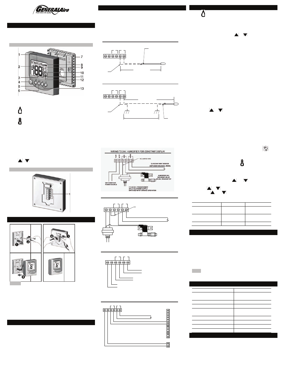
FRONT VIEW
1.
Operation modes
2.
Moisture is being added into the environment
3.
Humidity / temperature reading
4.
: Toggle between OFF, MANUAL and AUTO
modes (if outdoor sensor is connected)
5.
: Toggle between indoor humidity and indoor /
outdoor temperature displays (if outdoor sensor is
connected)
6.
°C / °F: Select temperature unit
7.
Wall mount cover. Squeeze top-bottom to open.
8.
Humidity index chart
9.
Outdoor temperature reading is displayed
10. Temperature / humidity setting is displayed
11. Temperature / humidity offset is displayed
12. Indoor temperature / humidity reading is displayed
13.
/
: Increase / decrease setting; enter
humidity / temperature offset setting
BACK VIEW
14.
14.
Removable terminal block for wire connections.
TO MOUNT THE UNIT
NOTES
•
To remove the humidistat from the base, squeeze
the louvered base at the top and bottom.
•
To remove the humidistat from the wall, lift up on
the humidistat and pivot top away from wall
•
Before wall mounting, please remove the gasket.
•
Before return air duct mounting, please remove the
breakout piece. Remove terminal block for wiring.
•
If return air duct mounting, route wires between
humidistat and base.
MOUNT THE OUTDOOR SENSOR
Mount the sensor outside the house:
•
Do not mount on South side of the house or in
direct sunlight.
•
Place at least 4 feet away from any exhaust vent.
•
If in air intake, place 1 foot or closer to outside wall.
•
Place at least 6” higher than possible snow.
•
Do not route sensor wire near high voltage wires.
WIRING
WIRING TO 24V. BYPASS HUMIDIFIER
A
C
L
A
C
N
H
U
M
SN
SR
OUTDOOR TEMP. SENSOR
(NOT USED IN MANUAL MODE)
HUMIDIFIER 24V.
SOLENOID VALVE
OR 24V. DRUM MOTOR
727-58 24 V. TRANSFORMER
OR 24 VAC POWER SUPPLY
SWITCHED WITH FURNACE OPER ATION
JUMPER WIRE
24V OUTPUT FROM HUMIDIFIER (RED WIRES) OR
727-58 24 V. TRANSFORMER SWITCHED WITH FURNACE O R
OR 24 VAC POWER SUPP LY SWITCHED WITH FURNACE.
WIRING TO 1137, 1000 POWER HUMIDIFIER
HUMIDIFIER CONTROL LEADS
(YELLOW WIRES)
OUTDOOR TEMP. SENSOR
(NOT USED IN MANUAL MODE)
AC L
AC N
HUM
SNSR
WIRING TO DS-15, RS-15, CS-15, DS-35,
RS-35, CS-35 ELITE STEAM HUMIDIFIER
AC L
AC N
HUM
SNSR
OUTDOOR TEMP. SENSOR
(NOT USED IN MANUAL MODE)
N2
GND
GND
GND
N1
AB
AB
IN
NO
NO
C
C
NC
24V
AL
ARM
EX
T
FA
N
TO USE THE UNIT
Press
to select OFF, MANUAL or AUTO mode (if
outdoor sensor is connected).
• OFF mode: The humidifier is turned off.
• MANUAL mode: The E2 will work to maintain the
single humidity selected. You can set your desired
humidity level by pressing
or
. The humidifier
will turn ON or OFF according to your manual setting.
(The humidifier will operate when the measured
relative humidity falls more than 2% below the set
point.) Humidity will have to be lowered when weather
is colder or if condensation is suspected.
Suggested Setting Outdoor Temperatures
15%
-20
-29
20%
-10
-23
25%
0
˚F -18˚C
˚F
˚C
˚F
˚C
˚F
˚C
˚F
˚C
˚F
˚C
30%
+10
-12
35%
+20
- 7
40%
+30
- 1
• AUTO mode: The E2 will automatically raise the
humidity as the outdoor temperature increases. This
provides the highest possible humidity. The E2 will
automatically lower the humidity as temperatures
drop. This minimizes the risk of condensation on cold
surfaces like windows. You can adjust the Auto
Humidity Index Set Point from 0 (low) to 10 (high) by
pressing
or
. The Humidity Index is based on
the outdoor temperature and indoor humidity. The
humidifier will switch ON/OFF according to the
calculated auto humidity index set point. Lower Index
settings are for older homes with less insulation and
vapor barriers. Higher Index settings are for newer
homes with complete vapor barriers, triple pane
windows and high R-value insulation. If condensation
occurs reduce Index setting by 2 points until
condensation stops.
NOTE If the outdoor temperature sensor fails,
flashes and the unit will default to MANUAL mode.
• To toggle between indoor / outdoor temperature
and indoor humidity: Press
.
• To change the temperature unit: Press °C / °F.
• To set the temperature / humidity offset in
MANUAL or AUTO mode:
1. Simultaneously press
and
when viewing the
temperature or humidity reading.
2. Use
or
to change the setting (-3 to 3).
3. Press
and
simultaneously or wait 5
seconds to confirm and move onto the next setting.
• Lo or Hi will flash on the display when:
MEASUREMENT
LO
HI
Indoor temp.
Below 0
o
C
(32
o
F)
Above
99
o
F(37
o
C)
Outdoor temp.
Below -40
o
C
(-40
o
F)
Above 50
o
C
(122
o
F)
Humidity
Below 10%
Above 90%
• If power is lost, current settings are retained.
PRECAUTIONS
This product is engineered to give you years of
satisfactory service. Here are a few precautions:
•
Do not allow excess humidification. Excess
humidity can cause condensation and enable mold
and mildew growth.
•
Do not tamper with the unit’s internal components.
The unit contains no user-serviceable parts.
•
The contents of this manual may not be reproduced
without the permission of the manufacturer.
NOTE The technical specifications for this product and
the contents of the user manual are subject to change
without notice.
SPECIFICATIONS
TYPE
DESCRIPTION
Dimensions
H x W x D
84 x 84 x 20 mm
(3.3 x 3.3 x 0.8 in.)
Weight
95.4 g (3.4 ounces)
Temperature unit
°F / °C
Temperature operating
range
32°F to 99°F
-0°C to 37°C
Temperature resolution
2°F (1 °C)
Humidity range
10% to 60%
Humidity resolution
1%
Power
18-30 Volts, AC
TECHNICAL SUPPORT
General Filters, Inc. Tel: 248-476-5100
43800 Grand River [email protected]
Novi, MI 48375 Form 13144 REV. F.
•
If Outdoor Temperature is over 50°F or 10°C, a safety
stop will prevent calling for humidity. Test circuit by
removing one outdoor sensor wire.
•
Confirm correct outdoor temperature reading. If
temperature reading is high, use Diagram for
GREATER THAN 20 FEET.
WIRING OUTDOOR SENSOR LESS THAN 20 FEET
SNSR
HUM
ACN
ACL
WIRING OUTDOOR SENSOR GREATER THAN 20 FEET
SPLICES: NO MORE THAN
ONE PER LEAD.
20 FEET MAX.
SNSR
HUM
ACN
ACL
SPLICES: NO
MORE THAN
ONE PER
LEAD.
300 FEET MAX.
COMMON GROUND
COMMON GROUND examples:
Water pipe, metal duct, household electrical safety ground, conduit.
The wire from the unit and the wire from the sensor must both be
connected to the same common ground, for example both to water
pipe OR both to the household safety ground.
NOTE: Separate sensor and common ground by at least 4 inches.
Ex: Don’t lay the wire on the metal conduit or duct used for the ground.
FIELD
SUPPLIED
FIELD
SUPPLIED
®