QTech Data Systems DNP3 RTU User Manual
Page 26
DATRAN XL4 RTU – Owners Manual – v1.1 June 2012
www.qtech.co.nz
Page 26
Configuration Jumper
Configuration Jumper
Configuration Jumper
Configuration Jumper Locations
Locations
Locations
Locations
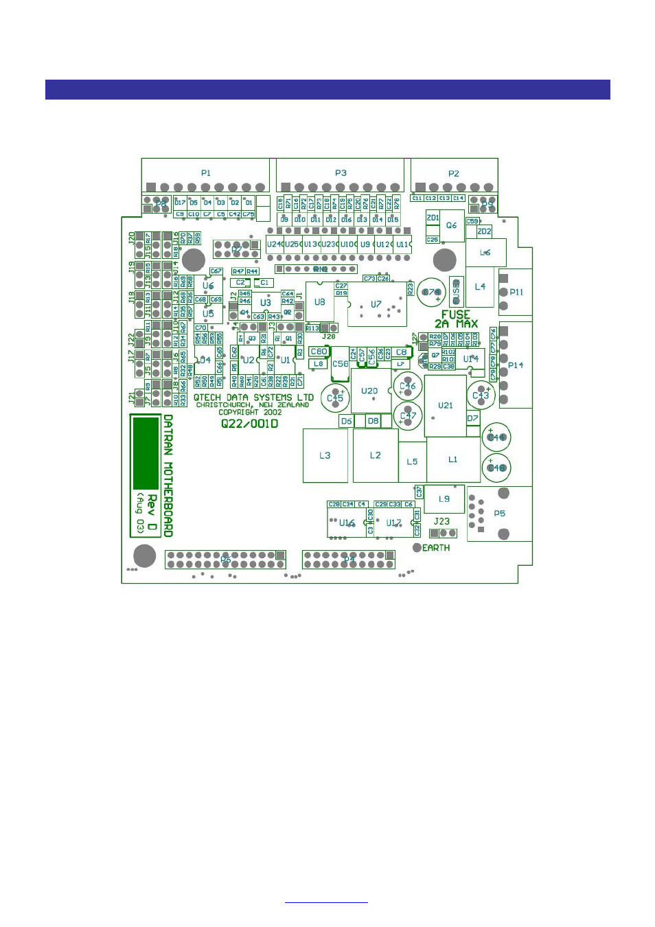
The diagram below shows the general location of each of the configuration jumpers on the Q22 I/O board. The
precise location, orientation and identification of jumper pin numbers is best done by referring to the diagrams in
this manual and referring to an actual Q22 I/O board.
Location of Configuration Jumpers on Q22 I/O board.
In the diagrams shown the square pad on each jumper header is pin No 1. The pins are numbered 1, 2, and 3
away from pin No 1. Orientation of pin No 1 of the jumpers on the actual Q22 I/O board can vary.
TIP
A pair of fine pointed nosed pliers or tweezers can be used to remove and install the jumper shorting links.
The jumper shorting links will only fit onto the jumper pins one way. Always check that they are seated
properly.
Unused or open jumper shorting links may be installed on only one pin of the jumper