Analog i/o configuration jumpers – QTech Data Systems DNP3 RTU User Manual
Page 22
DATRAN XL4 RTU – Owners Manual – v1.1 June 2012
www.qtech.co.nz
Page 22
Analog I/O Configuration Jumpers
Analog I/O Configuration Jumpers
Analog I/O Configuration Jumpers
Analog I/O Configuration Jumpers
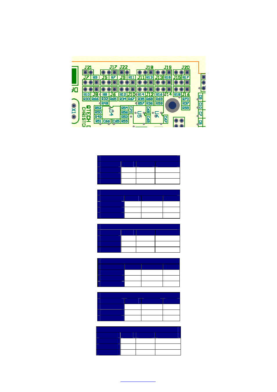
The analog input configuration jumpers are located at the top right region of the Q22 when viewed with the Q24 on
the right and the Q04 Processor board removed. The square pad on each jumper header is indicates pin 1. The
pins are numbered 1, 2, and 3 away from pin 1.
Analog input configuration jumpers.
The following tables show the jumper configurations of analog channel when configured as Single Ended Inputs.
Channel No 1 – Single Ended Input
J7
J8
J21
0..5V
2 - 3
OPEN
INSTALL
0..10V
1 - 2
2 - 3
INSTALL
0..20mA
2 - 3
1 - 2
INSTALL
Channel No 2 – Single Ended Input
J5
J6
J17
0..5V
2 - 3
OPEN
2 - 3
0..10V
1 - 2
2 - 3
2 - 3
0..20mA
2 - 3
1 - 2
2 - 3
Channel No 3 – Single Ended Input
J9
J10
J22
0..5V
2 - 3
OPEN
INSTALL
0..10V
1 - 2
2 - 3
INSTALL
0..20mA
2 - 3
1 - 2
INSTALL
Channel No 4 – Single Ended Input
J11
J12
J18
0..5V
2 - 3
OPEN
2 - 3
0..10V
1 - 2
2 - 3
2 - 3
0..20mA
2 - 3
1 - 2
2 - 3
Channel No 5 – Single Ended Input
J13
J14
J19
0..5V
2 - 3
OPEN
2 - 3
0..10V
1 - 2
2 - 3
2 - 3
0..20mA
2 - 3
1 - 2
2 - 3
Channel No 6 – Single Ended Input
J15
J16
J20
0..5V
2 - 3
OPEN
2 - 3
0..10V
1 - 2
2 - 3
2 - 3
0..20mA
2 - 3
1 - 2
2 - 3
The following tables show the jumper settings for configuring analog input channels 1 & 2 and/or 3 & 4 as
Differential Input channels: -