QTech Data Systems DNP3 RTU User Manual
Page 23
DATRAN XL4 RTU – Owners Manual – v1.1 June 2012
www.qtech.co.nz
Page 23
Channel No 1 & 2 – Differential Input
J7
J8
J17
J21
0..5V
2 - 3 OPEN 1 - 2 OPEN
0..10V
1 - 2
2 - 3
1 - 2 OPEN
0..20mA
2 - 3
1 - 2
1 - 2 OPEN
Channel No 3 & 4 – Differential Input
J9
J10
J18
J22
0..5V
2 - 3 OPEN 1 - 2 OPEN
0..10V
1 - 2
2 - 3
1 - 2 OPEN
0..20mA
2 - 3
1 - 2
1 - 2 OPEN
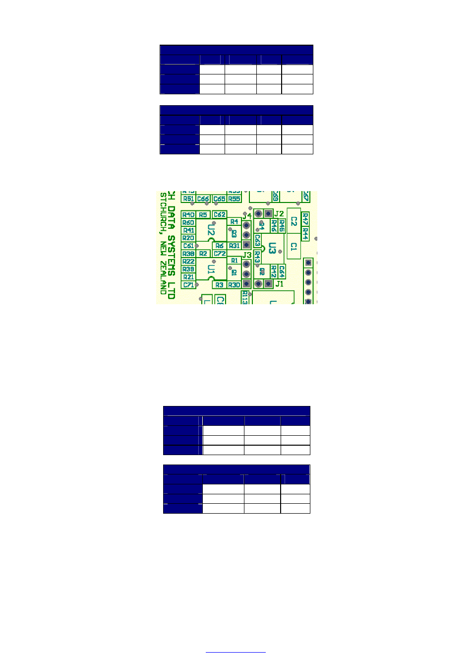
The analog output configuration jumpers are located at the centre upper right hand side of the Q22 as viewed with
the front display panel to the right and the Q04 Processor board removed.
Analog output configuration jumpers.
The diagram above shows the location of the jumpers used to configure the analog output channels. The square
pad on each jumper header is pin No 1. The pins are numbered 1, 2, and 3 away from pin No 1.
The following two tables show the jumper configurations for analog channels 5 and 6 when configured as single
ended output channels.
Note. Single ended output means that the output voltage or current is referenced to ground. That is, the negative
side of the output is at ground potential (the ‘G’ terminal on the ANALOG I/O port).
Channel No 5 – Single Ended Output
J2
J4
J19
0..5V
OPEN
2 - 3
1 - 2
0..10V
INSTALL
2 - 3
1 - 2
0..20mA
OPEN
1 - 2
1 - 2
Channel No 6 – Single Ended Output
J1
J3
J20
0..5V
OPEN
2 - 3
1 - 2
0..10V
INSTALL
2 - 3
1 - 2
0..20mA
OPEN
1 - 2
1 - 2
Note. When an analog output channel is to be configured for 4 to 20mA output, configure the channel’s jumpers
for 0 to 20mA output. Then use Workbench to configure the analog output channel as 4 to 20mA.