QTech Data Systems DNP3 RTU User Manual
Page 21
DATRAN XL4 RTU – Owners Manual – v1.1 June 2012
www.qtech.co.nz
Page 21
Ana
Ana
Ana
Analog Outputs
log Outputs
log Outputs
log Outputs
Single Ended Output Details
Single Ended Output Details
Single Ended Output Details
Single Ended Output Details
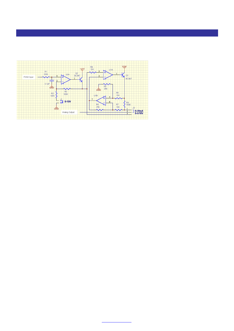
The diagram below shows the single ended analog output circuit. The circuit includes PWM input preconditioning,
low impedance 5V/10V voltage output circuit and a voltage to current converter.
Circuit details of Single Ended Analog Output Channel.
The following paragraphs describe the various single ended Analog output configurations:
0 to 5V
In this configuration jumper J1 is left open and jumper J3 has pins 2 & 3 closed. The op-amp U3A
operates as a unity gain amplifier. Q2 provides low impedance output drive.
0 to 10V
J1 is closed and jumper J3 has pins 2 & 3 closed. The op-amp U3A operates as a 2 x gain
amplifier. Q2 provides low impedance output drive.
0 to 20mA
In this configuration jumper J1 is left open and jumper J3 has pins 1 & 2 closed. The op-amp U3A
operates as a unity gain amplifier. Op-amps U1A & U1B form a voltage to current converter.
4 to 20mA
The 4 to 20mA loop configuration is the same as the 0 to 20mA loop described above, except the
central processor scales the output to 4 to 20mA range. This reduces the DAC resolution to 80%
of the 256 counts for full scale to 1 part in 205 counts.