QTech Data Systems DNP3 RTU User Manual
Page 16
DATRAN XL4 RTU – Owners Manual – v1.1 June 2012
www.qtech.co.nz
Page 16
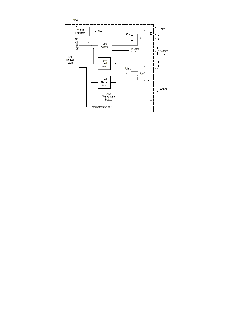
Circuit details of a Digital Output Channel.
The digital output MOSFET transistors have an ON resistance of typically 1 ohm and are capable of switching 3
amps at 5.5 to 26.5 volts. The output voltage is clamped at 65 volts to help reduce the effects of voltage spikes
when switching inductive loads. It is still recommended good practice that such loads be fitted with their own fly
back or free-wheeling diode.
Note. The total digital switching current is limited to approximately 1.5 amps by the DATRAN XL4 internal 2 amp
fuse.
Output Protec
Output Protec
Output Protec
Output Protection
tion
tion
tion
Each digital output channel is protected against over-current and over-temperature conditions. The over-current
protection will activate if the current being sourced through a given channel exceeds nominally 4 A.
The default behaviour is that if an over-current fault is detected on a given channel, then that channel will be turned
OFF and remain OFF until the over-current fault clears.
By removing jumper J28 the behaviour can be changed to be if an over-current fault is detected on a given
channel, then that channel will be put into current-limit mode. While in current-limit mode, the output current on that
channel will be limited to 500mA until such time as the over-current fault clears (provided thermal shut down has
not occurred also).
Jumper J28 is located at the centre lower right hand side of the Q22 as viewed with the front display panel to the
right and the Q04 Processor removed.