Timing characteristics, Electrical characteristics (continued) – Rainbow Electronics MAX547 User Manual
Page 3
MAX547
Octal, 13-Bit Voltage-Output
DAC with Parallel Interface
_______________________________________________________________________________________
3
Note 1:
PSRR is tested by changing the respective supply voltage by ±5%.
Note 2:
For best performance, REF_ should be greater than AGND_ + 2V and less than V
DD
- 0.6V. The device operates with
reference inputs outside this range, but performance may degrade. For further information on the reference, see the
Reference and Analog-Ground Inputs section in the Detailed Description.
Note 3:
Reference input resistance is code dependent. See
Reference and Analog-Ground Inputs section in the Detailed
Description.
Note 4:
Typical settling time with 1000pF capacitive load is 10µs.
Note 5:
Guaranteed by design. Not production tested.
Note 6:
Guaranteed by supply-rejection test.
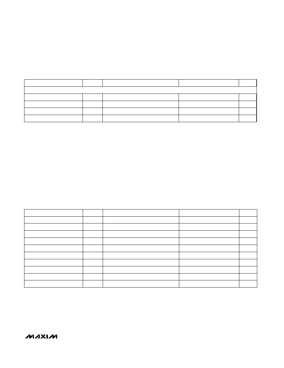
TIMING CHARACTERISTICS
(V
DD
= +5V, V
SS
= -5V, REF_ = 4.096V, AGND_ = GND = 0V, T
A
= T
MIN
to T
MAX
, unless otherwise noted.)
14
44
11
40
T
A
= T
MIN
to T
MAX
mA
I
SS
Negative Supply Current
CONDITIONS
mA
I
DD
Positive Supply Current
V
-5.25
-4.75
V
SS
Negative Supply Range
V
4.75
5.25
V
DD
Positive Supply Range
UNITS
MIN
TYP
MAX
SYMBOL
PARAMETER
(Note 6)
(Note 6)
CONDITIONS
ns
0
t
6
–
C
—
S
–
High to
–
W
—
R
–
High
ns
0
t
5
–
C
—
S
–
Low to
–
W
—
R
–
Low
ns
100
t
4
–
C
—
L
—
R
–
Pulse Width Low
ns
50
t
3
–
L
—
D
—
–
–
Pulse Width Low
ns
50
t
2
–
W
—
R
–
Pulse Width Low
ns
50
t
1
–
C
—
S
–
Pulse Width Low
UNITS
MIN
TYP
MAX
SYMBOL
PARAMETER
ns
50
t
7
Data Valid to
–
W
—
R
–
Setup
ns
0
t
8
Data Valid to
–
W
—
R
–
Hold
ns
10
t
9
Address Valid to
–
W
—
R
–
Setup
ns
0
t
10
Address Valid to
–
W
—
R
–
Hold
ELECTRICAL CHARACTERISTICS (continued)
(V
DD
= +5V, V
SS
= -5V, REF_ = 4.096V, AGND_ = GND = 0V, R
L
= 10k
Ω
, C
L
= 50pF, T
A
= T
MIN
to T
MAX
, unless otherwise noted.
Typical values are at T
A
= +25°C.)
T
A
= T
MIN
to T
MAX
POWER SUPPLIES