Max547, Table 4. max547 positive unipolar code table, Table 3. max547 bipolar code table – Rainbow Electronics MAX547 User Manual
Page 10
10
______________________________________________________________________________________
MAX547
Positive Unipolar Output Voltage Range
(AGND_ = REF_/2)
For positive unipolar output operation, set AGND_ to
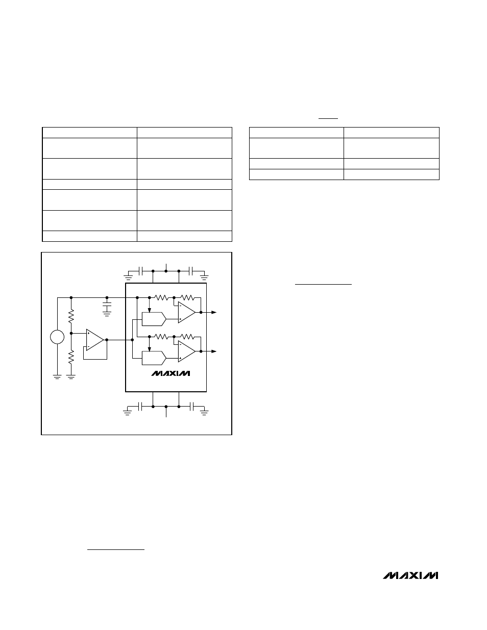
(REF_/2). For example, if you use Figure 4’s circuit with,
a 4.096V reference and offset AGND_ by 2.048V with
matched resistors (R1 = R2) and an op amp, it results in
a 0V to 4.0955V (nominal) unipolar output voltage,
where 1LSB = 500µV. In general, the maximum current
flowing out of any AGND_ pin is given by:
Customizing the Output Voltage Range
The AGND_ inputs can be offset by any voltage within the
supply rails if the voltage at the referring REF_ input is
higher than the voltage at the AGND_ input. Select the
reference voltage and the voltage at AGND_ so the
resulting output voltages do not come within ±0.6V of the
supply rails. Figure 4’s circuit shows one way to add posi-
tive offset to AGND_; make sure that the op amp used
has sufficient current-sink capability to take up the
remaining AGND_ current:
Another way is to digitally offset AGND_ by connecting
the output of one DAC to one or more AGND_ inputs. Do
not connect a DAC output to its own AGND_ input.
Table 5 summarizes the relationship between the refer-
ence and AGND_ potentials and the output voltage in
the different modes of operation.
Power-Supply Sequencing
The sequence in which the supply voltages come up is
not critical. However, we recommend that on power-up,
V
SS
comes up first, V
DD
next, followed by the reference
voltages. If you use other sequences, limit the current
into any reference pin to 10mA. Also, make sure that
V
SS
is never more than 300mV above ground. If there is
a risk that this can occur at power-up, connect a
Schottky diode between V
SS
and GND, as shown in
Figure 5. We recommend that you not power up the
logic input pins before establishing the supply volt-
ages. If this is not possible and the digital lines can
drive more than 10mA, you should place current-limit-
ing resistors (e.g., 470
Ω
) in series with the logic pins.
Reference Selection
If you want a ±2.5V full-scale output voltage swing, you
can use the MAX873 reference. It operates from a sin-
gle 5V supply and is specified to drive up to 10mA.
Therefore, it can drive all four reference inputs simulta-
neously. Because the maximum load impedance can
vary from 1.25k
Ω
to 12.5k
Ω
(four reference inputs in
parallel), the reference load current ranges from 2mA to
0.2mA (1.8mA maximum load step). The MAX873’s
I
REF_
AGND_
5k
AGND_
=
−
Ω
I
REF_
AGND_
5k
AGND_
=
−
Ω
Octal, 13-Bit Voltage-Output
DAC with Parallel Interface
OUTPUT
INPUT
4095
+REF_
(
———
)
4096
1 1111 1111 1111
0V
1 0000 0000 0000
1
+REF_
(
———
)
4096
1 0000 0000 0001
1
-REF_
(
———
)
4096
0 1111 1111 1111
4095
-REF_
(
———
)
4096
0 0000 0000 0001
-REF_
0 0000 0000 0000
+5V
1
µ
F
REFAB
AGNDAB
1
µ
F
R1
REF
R2
V
DD
V
DD
DIGITAL INPUTS NOT SHOWN.
NOT ALL DACS SHOWN.
1
µ
F
VOUTA
VOUTB
DAC B
DAC A
MAX547
-5V
V
SS
V
SS
1
µ
F
1
µ
F
+REF– /2
1 0000 0000 0000
OUTPUT
0V
0 0000 0000 0000
INPUT
8191
+REF_
(
———
)
8192
1 1111 1111 1111
Table 4. MAX547 Positive Unipolar Code Table
(AGND_ = REF
_)
2
Table 3. MAX547 Bipolar Code Table
(AGND_ = 0V)
Figure 4. Offsetting AGND–