Optional electronic control system, Parts list – United States Stove Company 1800 User Manual
Page 21
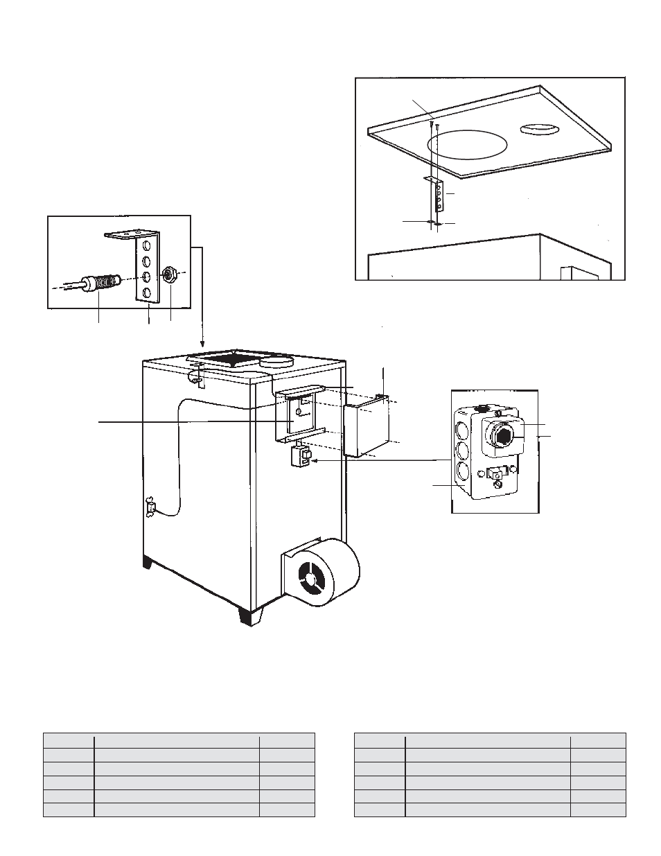
OPTIONAL ELECTRONIC CONTROL SYSTEM
6
5
9
7
8
8
4
1
2
3
INSTALLATION INSTRUCTIONS
1.
Remove top of furnace.
2.
Attach heat sensor "L" bracket to pins located on
underside of furnace top (see illustration).
3.
Mount heat sensor in "L" bracket and run cable from
sensor between insulation and furnace top.
4.
Feed cable down behind back insulation and pull cable
through hole on back of furnace.
5.
Attach control box to back of furnace and wire per
instructions.
MOUNTING
PINS
"L" BRACKET
PIN TABS
19
10
ITEM
DESCRIPTION
PART#
1
Heat Sensor
C47314
2
Heat Sensor Mounting Clip
CL00084
3
3/8" Hex Nut
C20699
4
Electronic Circuit Board - 1988
C45599
5
Circuit Board Box
CL00087
6
Box Cover
CL00085
7
Utility Box Cover
C40399
8
10 Amp Fuse - W10 Fast Blow
C40499
9
Raco Box
C40299
10
Pin Tabs
C99799
ITEM
DESCRIPTION
PART#
PARTS LIST
MODEL 1600 / 1800