Connections with the iss-6020, Connections with one iss-6020 switcher – NEC GT2000 User Manual
Page 28
E-28
Connections with the ISS-6020
Connections with One ISS-6020 Switcher
Connecting your GT2000/GT2000R projector to a single ISS-6020 switcher (using a cable available separately) delivers a
series of benefits:
• You can handle input from ten sources simultaneously.
• The ISS-6020 can be controlled by the remote provided with your GT2000/GT2000R or with the buttons on the projector
cabinet. (Source selection without the use of a CTL-6010 cable must be performed with the GT2000 hand held remote
control.)
• “Channel Memory” enables you to set optimal settings individually for as many as ten different sources.
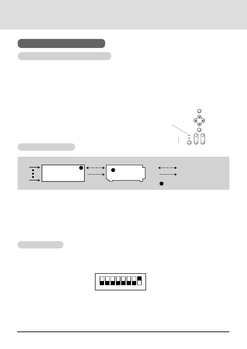
System Connections Diagram
To use the ISS-6020 with the GT2000/GT2000R, do the following:
* Select the [Settings Menu]
→
[Switcher Control]
→
[SW 1 Level] under the main menu.(The factory default setting is
"Standalone".)
* Select the [Memory]->[Channel Memory] under the main menu and perform the Signal Entry.
* When using the projector with the external equipment, select the [Memory]->[User Memory] under the main menu and
perform the Signal Entry.
* Select the [Switcher] menu from the main menu and make some adjustments such as RGB gain, color, tint, sharpness,
volume and audio control.
To use GT2000/GT2000R with an ISS-6020, the DIP switch (S8601) located inside the ISS-6020 System Control module
should be set as shown here. (Leave the pins 5 to 7 in their original factory settings.)
* For more details about operating the ISS-6020, please see your ISS-6020 user's manual
DIP Switch Settings
Lights green
When the GT2000/GT2000R is used with the ISS-6020 switcher in
bundled operation, the indicator LED (STATUS) lights green after
switching on the GT2000/GT2000R power.
MENU
SELECT
ENTER
STATUS
ZOOM
FOCUS
POWER
ON / OFF
-
+
-
+
-
+
GT2000
GT2000R
ISS-6020
1
1
1
indicates the REMOTE 1 connector
Control cable
Video signal cable
1
10
1
2
3
4
5
6
7
8
SHORT
OPEN
Pin No.8 must be set at "OPEN".