Interface cable connector, User’s guide 125 – PSC PT2000 User Manual
Page 135
Interface Cable Connector
User’s Guide
125
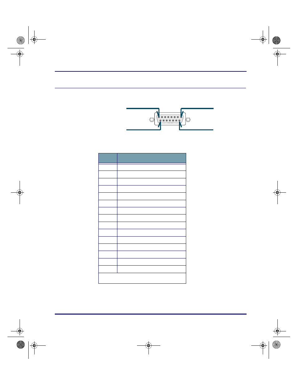
Interface Cable Connector
Figure F-2: Interface Cable Connector Pinouts
Table F-2: Interface Cable Connector Pinouts
Pin #8
Pin #1
Pin #15
Pin #9
Pin #
Description
1
Shield
2
Transmit data out
3
Receive data in
4
Hardware handshake out*
5
Hardware handshake in
6
Not used
7
Ground
8
Cable detect
9
+5V in
10
+9V in
11
485+
12
485-
13
Wedge clock
14
Wedge data
15
Wedge keyboard enable
* Must be connected to CTS or hardware
handshake out on the computer.
PT2000.book Page 125 Thursday, February 26, 2004 9:34 AM
This manual is related to the following products: