Infinity DMC 1000 User Manual
Page 106
106
DMC 1000 Digital Media Camcorder User’s Guide (v1.15)
Chapter 11 - Specifications
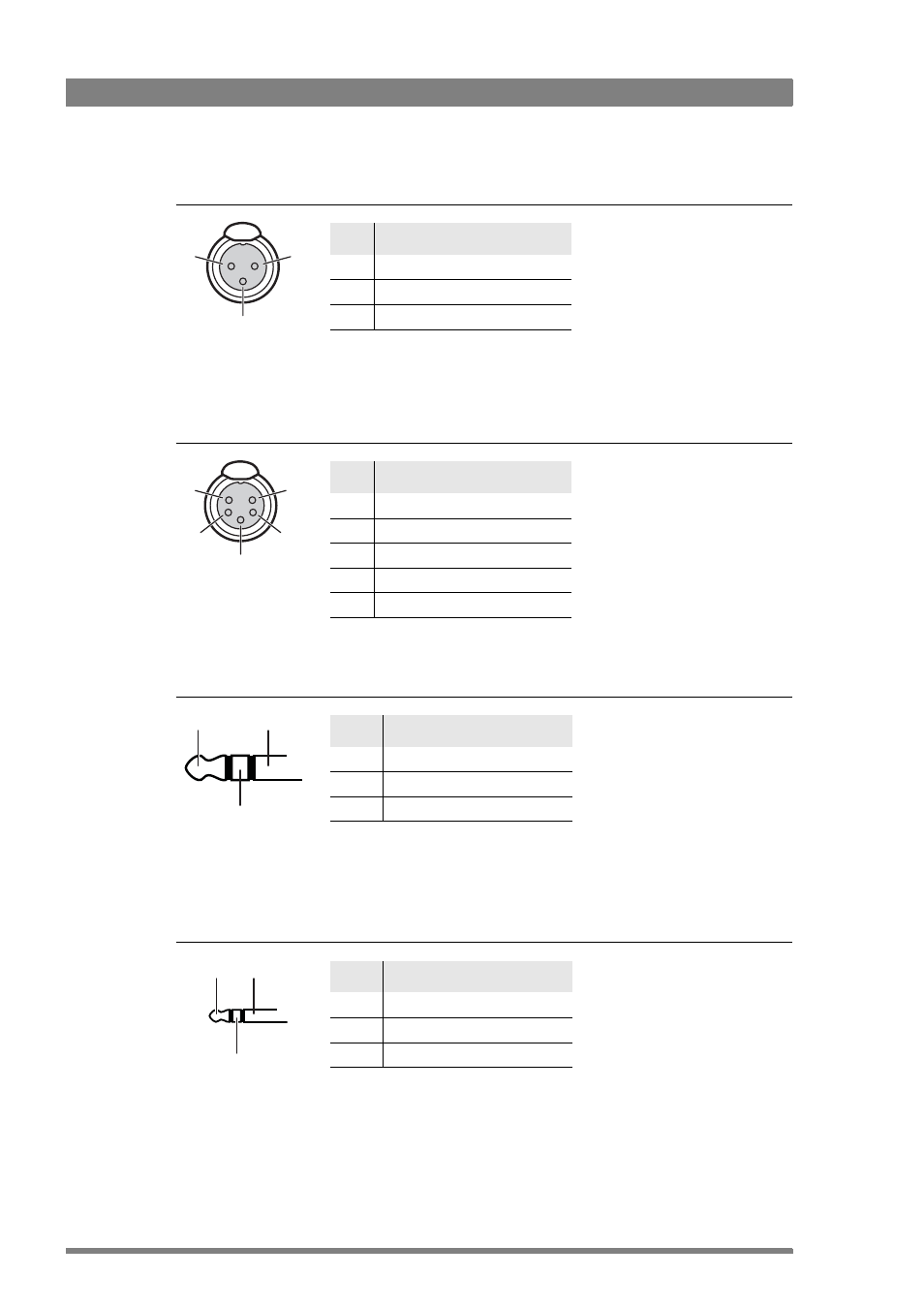
Front microphone connector XLR-3 (Front1)
Front microphone connector XLR-5 (Front1 and Front2)
Headphones output
Headset microphone input (MicRear)
Pin
Description
1
Chassis ground (cable shield)
2
Audio (+)
3
Audio (-)
XLR 3-pin female
(panel view)
Microphone impedance: 200
Ω
Max. input level: +14 dBu
Phantom power: +48 V (fixed)
3
1
2
Pin
Description
1
Chassis ground (cable shield)
2
Audio 1 hot (+)
3
Audio 1 cold (-)
4
Audio 2 hot (+)
5
Audio 2 cold (-)
XLR 5-pin female
(panel view)
2
3
1
4
5
Microphone impedance: 200
Ω
Max. input level: +14 dBu
Phantom power: +48 V (fixed)
Pin
Description
sleeve
Ground (cable shield)
tip
Audio Left
ring
Audio Right
Headphones impedance: 200
Ω
Max. output level: +22 dBu
sleeve
ring
tip
6.3 mm jack
(cable plug shown)
Pin
Description
sleeve
Ground (cable shield)
tip
Signal hot (+)
ring
signal cold (-)
Microphone impedance: 200
Ω
Max. input level: +14 dBu
Phantom power: +5 .. +7 V (fixed)
Note: for unbalanced operation the
ring and sleeve should be internally
bridged.
sleeve
ring
tip
3.5 mm mini jack
(cable plug shown)