Harbor Freight Tools GREYHOUND 65761 User Manual
Page 12
SKU 65761
For technical questions, please call 1-800-444-3353.
Page 12
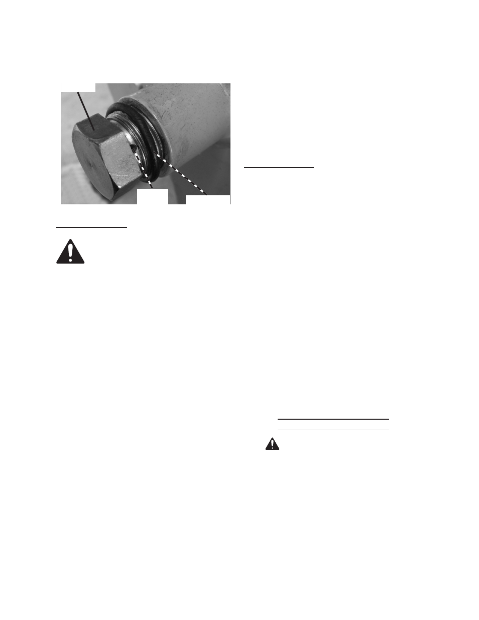
air inlet hole by tightening the Plug,
as shown below.
plug (37)
o ring (21)
air inlet
Hole
start procedure
Before starting the engine:
Follow the set up instruc-
a.
tions to prepare the equip-
ment.
inspect the equipment and
b.
engine.
Fill the engine with the prop-
c.
er amount and type of fuel
and oil.
read the equipment opera-
d.
tion section that follows.
Turn the engine fuel valve to its
1.
“OPEN” position.
Turn the engine power switch to its
2.
ON or RUN position.
Then, turn the engine choke lever to
3.
its “CHOKE” position. Set the choke
lever in the “RUN” position when
starting a warm engine.
Grasp the starter handle, and pull
4.
slowly until resistance is felt. While
holding the handle, allow the starter
rope to rewind slowly. Then, pull the
starter handle with a rapid, full arm
stroke. Once again while holding
the handle, allow the rope to rewind
slowly. Repeat as necessary, until
the engine starts.
After the engine starts and warms
5.
up, slowly move the choke lever to its
“RUN” position.
IMPORTANT: Allow the engine to run
6.
at no load until warm (1-5 minutes).
Break-in period
Breaking-in the engine will help to
1.
ensure proper equipment and engine
operation, and will extend the en-
gine’s lifespan. The warranty is void
if the engine is not broken in properly.
The first 20 hours of operation is the
break-in period.
During the first 3 hours of use:
2.
Do not apply a heavy load to the
•
equipment.
Do not operate the engine at its
•
maximum speed.
After the first 20 hours of use:
3.
Change the engine oil.
•
Under normal operating conditions
subsequent maintenance follows the
schedule explained in the MAINTE-
NANCE AND SERVICING section.
equipment operation
1.
Warning! to avoid death or
serious injury; block each side of
both wheels of the Log Splitter before
starting a job.
In FIGURE 1, the Rail Assembly is
2.
shown in Horizon tal mode for opera-
tion and travel. In FIGURE 4 the unit
is shown in the vertical position. To
change positions, remove the Hair
Pin Clip (29) and the Push Pin (26).