Harbor Freight Tools GREYHOUND 65761 User Manual
Page 10
SKU 65761
For technical questions, please call 1-800-444-3353.
Page 10
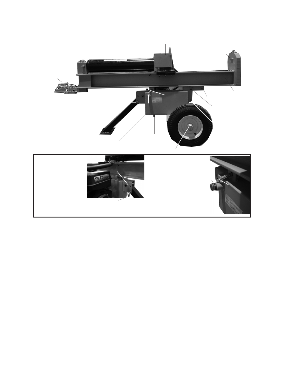
Hex Head Nut (17) is attached to Hex Head Bolt (16)
Rail Assembly
(2)
Hydraulic Oil Tank (10B)
Oil Plug (37)
with air inlet hole
Wheel Cap (61)
Figure 1
Safety Chain
with Hook (4)
Hitch
Coupler (9)
Front Leg Assembly (11)
Oil Drain Plug
Push Pin (26) and
Hair Pin Clip (29
)
Horizontal transport hole
Place Log Here
Cylinder (1)
Hex Head Nut (17) is
attached to Hex Head
Bolt (16)
Vertical position
locking hole
Figure 2
Figure 3
Push Pin (26)
Hydraulic Oil Fill Plug (37)
with air inlet ho
le
Close-up of Push Pin (26) securing the
Front Leg Assembly (11) to the bracket
on the Oil Tank Assembly (10B).
Second Push Pin (26) secures
Rail Assembly (2), and is removed
for vertical log splitting.
Horizontal transport hole
Air Inlet Hole
Slide Assembly (3)
Base
Vertical Position Hole
Push Pin (26)
- 2696 (4 pages)
- 92353 (8 pages)
- 04095 (14 pages)
- 92126 (12 pages)
- 42977 (4 pages)
- 67422 (2 pages)
- 40089 (4 pages)
- 65076 (18 pages)
- 6510 (16 pages)
- PROFASSIONAL 47214 (16 pages)
- 31877 (11 pages)
- HEAVY-DUTY 1/2" VSR DRILL 3273 (16 pages)
- CENTRALPNEUMATIC 97526 (10 pages)
- 18 GAUGE BRAD NAILER 68021 (18 pages)
- ONE STOP GARDENS 95692 (8 pages)
- 91054 (12 pages)
- 93100 (16 pages)
- 42597 (9 pages)
- 90310 (5 pages)
- 90320 (2 pages)
- 93142 (12 pages)
- 94434 (12 pages)
- CENTRAL PNEUMATIC 93305 (16 pages)
- 03664 (11 pages)
- 92421 (14 pages)
- 45949 (12 pages)
- 35559 (10 pages)
- CENTRAL MACHINERY 45861 (41 pages)
- MINI BENCH 4019 (14 pages)
- 47706 (7 pages)
- 67046 (12 pages)
- BENCH GRINDER 39797 (16 pages)
- 7528 (8 pages)
- 93197 (9 pages)
- 31849 (17 pages)
- Warrior 11 Piece Carbon Steel Hole Saw Set 68114 (4 pages)
- 54425 (10 pages)
- Pittsburgh Self-leveling Laser Level 69243 (8 pages)
- Drillmaster Palm Sander 98622 (12 pages)
- 50 FOOT DRAIN CLEANER WITH POWER FEED 68284 (24 pages)
- 65673 (16 pages)
- Chicago 46237 (19 pages)
- 93853 (18 pages)
- Drill Master 18V 3/8" Cordless Drill 67024 (12 pages)
- CENTRAL PNEUMATIC 92007 (10 pages)