Hearth and Home Technologies Heatilator GDST5244I User Manual
Page 35
Heatilator • GDST5244I • 4045-127 • Rev W • 11/08
35
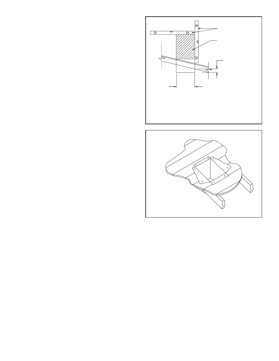
Cut hole 1/8 in. (3 mm) greater
in size than pattern of support
box as it is projected onto
roofline.
2 in. (51 mm)
minimum below
finished ceiling
Cathedral ceiling
support box
Level
F. Install Decorative Ceiling Components
(SLP only)
A decorative ceiling thimble can be installed on a fl at ceil-
ing through which the vent passes. The decorative ceiling
thimble is used to cover the fi restop.
• Seal the gap between the vent pipe and firestop
using high temperature silicone to prevent cold air
infi ltration.
• Install the decorative ceiling thimble by sliding it up to
the ceiling and attaching it using the provided screws.
A decorative cathedral ceiling support box can be used
where vertical vent runs pass through a cathedral ceiling.
• Use a plumb-bob to mark the center line of the venting
system on the ceiling and drill a small hole through the
ceiling and roof at this point. Locate the hole and mark
the outline of the cathedral ceiling support box on the
outside roof.
• Remove shingles or other roof covering as necessary
to cut the rectangular hole for the support box. Cut the
hole 1/8 in. (3 mm) larger than the support box outline.
• Lower the support box through the hole in the roof until
its bottom is at least 2 in. (51 mm) below the ceiling
(Figure 10.12).
• Level the support box both vertically and horizontally
and temporarily tack it in place through the inside walls
into the roof sheathing.
• Use tin snips to cut the support box from the top corners
down to the roof line and fold the resulting fl aps to the
roof. See Figure 10.13.
• Nail
the
fl aps to the roof AFTER running a bead of non
hardening sealant between the fl aps and the roof.
WARNING! Risk of Fire! Clean out ALL materials from
inside the support box and complete the vertical vent run
and termination.
Figure 10.12
Figure 10.13
G. Install Metal Roof Flashing
Note: Skip to Section 10.I. if using the RF4-8.
• See minimum vent heights for various pitched roofs
(Figure 10.14) to determine the length of pipe to extend
through the roof.
• Slide
the
roof
fl ashing over the pipe sections extending
through the roof as shown in Figure 10.15.