C. clear space, E. fixed glass assembly, D. decorative doors, fronts and surrounds – Heat & Glo Fireplace SUPREME-I30 User Manual
Page 8: H. control module operation, G. ipi battery tray/battery installation
Heat & Glo • Grand-I35, Grand-I35-SP, Supreme-I30, Supreme-I30-SP • 2206-900 Rev. K • 6/11
8
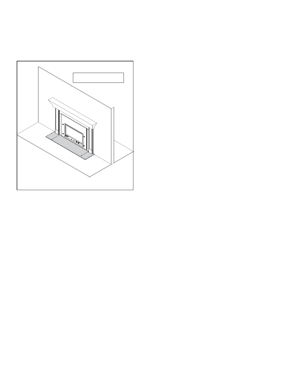
C. Clear Space
WARNING! DO NOT place combustible objects in front
of the fi replace or block louvers. High temperatures may
start a fi re. See Figure 2.2.
Avoid placing candles and other heat-sensitive objects on
mantel or hearth. Heat may damage these objects.
Figure 2.2 Clear Space
E. Fixed Glass Assembly
See
Section 12.H.
D. Decorative Doors, Fronts and Surrounds
WARNING! Risk of Fire! Install ONLY doors, fronts or
surrounds approved by Hearth & Home Technologies.
Unapproved doors or fronts may cause appliance to over-
heat.
This appliance has been supplied with an integral
barrier to prevent direct contact with the fi xed glass
panel. DO NOT operate the appliance with the barrier
removed.
Contact your dealer or Hearth & Home Technologies if
the barrier is not present or help is needed to properly
install one.
For more information refer to the instructions supplied with
your decorative door or front.
F. Remote Controls, Wall Controls and Wall
Switches
Follow the instructions supplied with the control installed
to operate your fi replace:
For safety:
• Install a switch lock or a wall/remote control with child
protection lockout feature.
• Keep remote controls out of reach of children.
See your dealer if you have questions.
CLEAR SP
ACE
3 FT
. IN FRONT OF FIREPLACE
APPLIANCE INSTALLED IN EXISTING
SOLID FUEL FIREPLACE
H. Control Module Operation
1. The control module has an ON/OFF/REMOTE selector
switch that must be set. See Figure 2.3.
OFF Position: Appliance will ignore all power inputs and
will not respond to any commands from a wall switch or
remote. The unit should be in the OFF position during
installation, service, battery installation, fuel conversion,
and in the event that the control goes into LOCK-OUT
mode as a result of an error code.
ON Position: Appliance will ignite and run continuously
in the HI fl ame setting, with no adjustment in fl ame
output. This mode of operation is primarily used for
initial installation or power outage operation with battery
backup.
REMOTE Position: Appliance will initiate commands
from an optional wired wall switch and/or the wireless
remote (RC300).
2. If using a wired wall switch with the module in REMOTE
mode, the fl ame output can be adjusted with the HI/LO
selector switch on the module. See Figure 2.3. Note
that the fl ame HI/LO selector switch will become inactive
once an optional remote control (RC200/RC300) is
programmed to the control module. Note that the control
module will always ignite the fi replace on HI and remain
so for the initial 10 seconds of operation. If the HI/LO
is switched to the LO position, the fl ame output will
automatically drop to the lowest setting after the fl ame
has been established for 10 sec. After this 10 second
period, the fl ame can be adjusted from HI to LO with
the switch.
3. The control module has safety feature that automatically
shuts down the fi replace after 9 hours of continuous
operation without receiving a command from the RC300
remote.
G. IPI Battery Tray/Battery Installation
The IntelliFire Plus
TM
system has a battery backup option.
Battery longevity and performance will be affected by the
service temperatures of this appliance.
NOTICE: Batteries should only be used as a power source
in the event of an emergency such as an outage.