35 operation – HONDA EM6500is User Manual
Page 37
35
OPERATION
AC Receptacle Selection
The generator has separate main power producing circuits. These two
circuits supply power to different receptacles shown when the voltage
selector switch is in the 120/240 V position.
When two or more receptacles are used, prevent overloading by
dividing the load between the two power circuits.
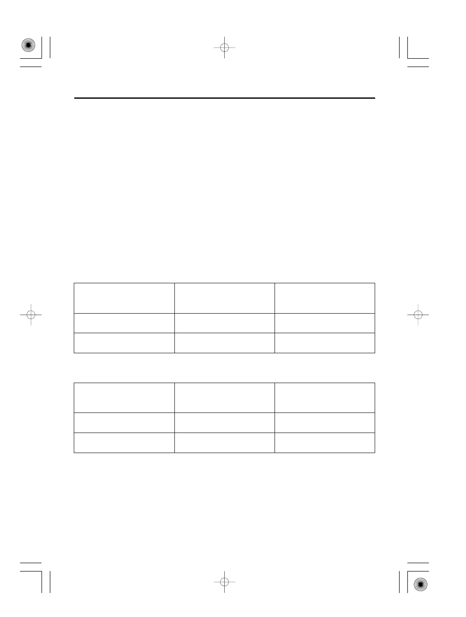
The chart below shows the rated load in amperes that can be
connected to each receptacle to balance the generator when the
120/240 V locking plug receptacle is used for 120 V.
The total rated ampere draw is:
Receptacles powered
by each main circuit
1, 3 and 4
2 and 5
Power distribution
1
3
4=18.8A rated.
2
5=18.8A rated.
Receptacles powered
by each main circuit
1, 3 and 4
2 and 5
Power distribution
1
3
4=22.9A rated.
2
5=22.9A rated.
Main power circuit
Main Circuit I
Main Circuit II
Main power circuit
Main Circuit I
Main Circuit II
37.5 A
45.8 A
EM5000is
EM5000is:
EM6500is:
EM6500is
07/03/13 16:25:37 31Z11600_036