2 installation diagrams, continued, Figure 3: connection diagram 2 – Honeywell HEGS5001 User Manual
Page 16
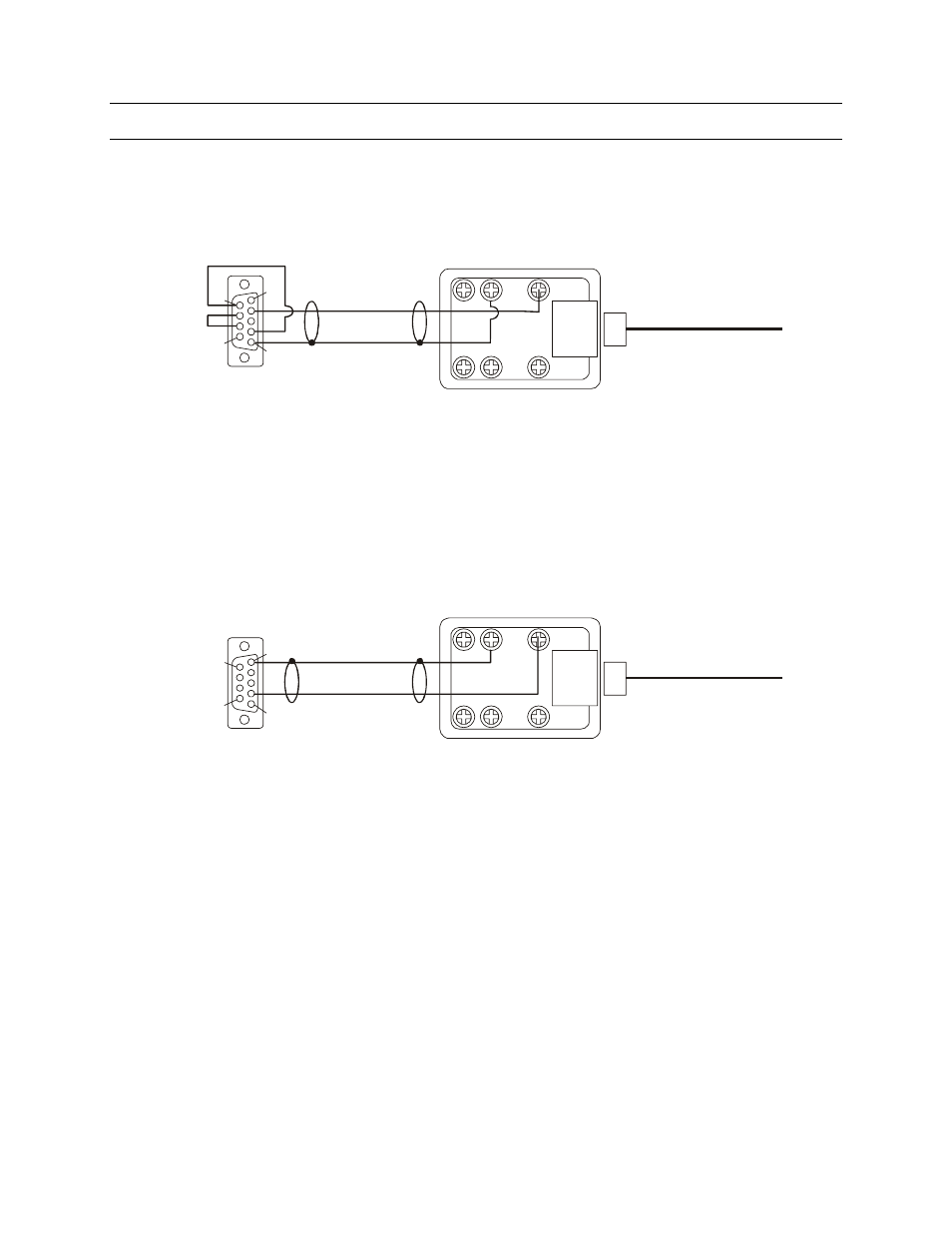
2.2 INSTALLATION DIAGRAMS, CONTINUED
+1
2
V
D
C
+12V
DC
GN
D
GN
D
R
S
-2
3
2
(T
X
)
R
S
-2
3
2
(T
X
)
R
S
-2
3
2
(R
X
)
RS
-2
32 (
RX
)
RS-232 VCR cable connections
RS-232 MUX cable connections
R
S
-4
8
5
(D
+
)
RS
-4
85 (
D+)
R
S
-4
8
5
(D
-)
RS
-485 (
D-
)
1
5
6
9
9
6
RS-232
to VCR
RS-232
to MUX
To HEGS5000
To HEGS5000
DB-9 Female
rear view of connector
DB-9 Male
rear view of connector
5
1
Figure 3: Connection Diagram 2
Rev. 1.01
6 900.0800
19-Jun-06
This manual is related to the following products: