Hitachi L2002 User Manual
Page 154
Using Intelligent Input Terminals
Oper
ations
and Monitor
ing
4–10
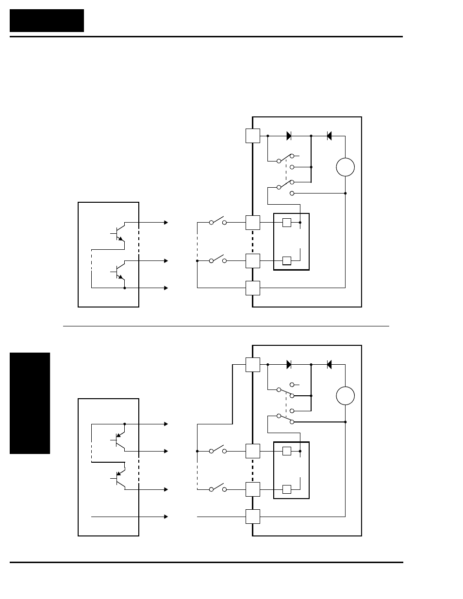
The two diagrams below show input wiring circuits using the inverter’s internal +24V
supply. Each diagram shows the connection for simple switches, or for a field device
with transistor outputs. Note that in the lower diagram, it is necessary to connect
terminal [L] only when using the field device with transistors. Be sure to use the correct
SR/SK switch position shown for each wiring diagram.
L200
2
L
24V
+
–
SK
SR
SK
SR
PCS
Input
circuits
1
5
Logic GND
1
5
GND
Open collector outputs,
NPN transistors
Input
switches
Sinking Inputs, Internal Supply
SR/SK switch = SK position
Field device
L200
2
L
24V
+
–
SK
SR
SK
SR
PCS
Input
circuits
1
5
Common,
to [PCS]
1
5
GND
PNP transistor
sourcing outputs
Input
switches
Sourcing Inputs, Internal Supply
SR/SK switch = SR position
Field device
to PNP bias
circuits
Logic GND
- C 7D (92 pages)
- DV18DMR (96 pages)
- DH 40FA (34 pages)
- SERIES D (28 pages)
- 231580 (34 pages)
- 206700 (24 pages)
- WH14DM OM (76 pages)
- DS 12DVF2 (4 pages)
- SJ-PB(T) (35 pages)
- NT 65M (4 pages)
- DH 40MRY (62 pages)
- RTX 900 (34 pages)
- DH 24DV (88 pages)
- FDS 9DVA (60 pages)
- L100 300 (16 pages)
- G13SE2 (52 pages)
- N 5008AC (42 pages)
- L300P (264 pages)
- DH 38YE (64 pages)
- CONVENTION 14 (305 pages)
- DS 14DVB (4 pages)
- H 45MR (52 pages)
- WH9DM2 (108 pages)
- B 16RM (64 pages)
- DH 24PD (28 pages)
- L300P Series (76 pages)
- W 8VB (52 pages)
- SJ2-CO (35 pages)
- CR 10DL (56 pages)
- DS18DVB2 (30 pages)
- WR 9DM (98 pages)
- CR 18DV (80 pages)
- 24PD (58 pages)
- SJ100 (214 pages)
- G 18MR (52 pages)
- 308640 (28 pages)
- DH 45MR (68 pages)
- NR90AA (48 pages)
- L100 (163 pages)
- 232624 (24 pages)
- SJ700-2 (284 pages)
- 288466 (14 pages)
- SJ-DG (20 pages)
- C6DD (22 pages)
- VARIABLE SPEED DV 18DV (68 pages)