Mounting the control, Wall mounting, Desktop mounting – Honeywell ADEMCO LYNXR-EN User Manual
Page 5
–5–
Mounting the Control
Wall Mounting
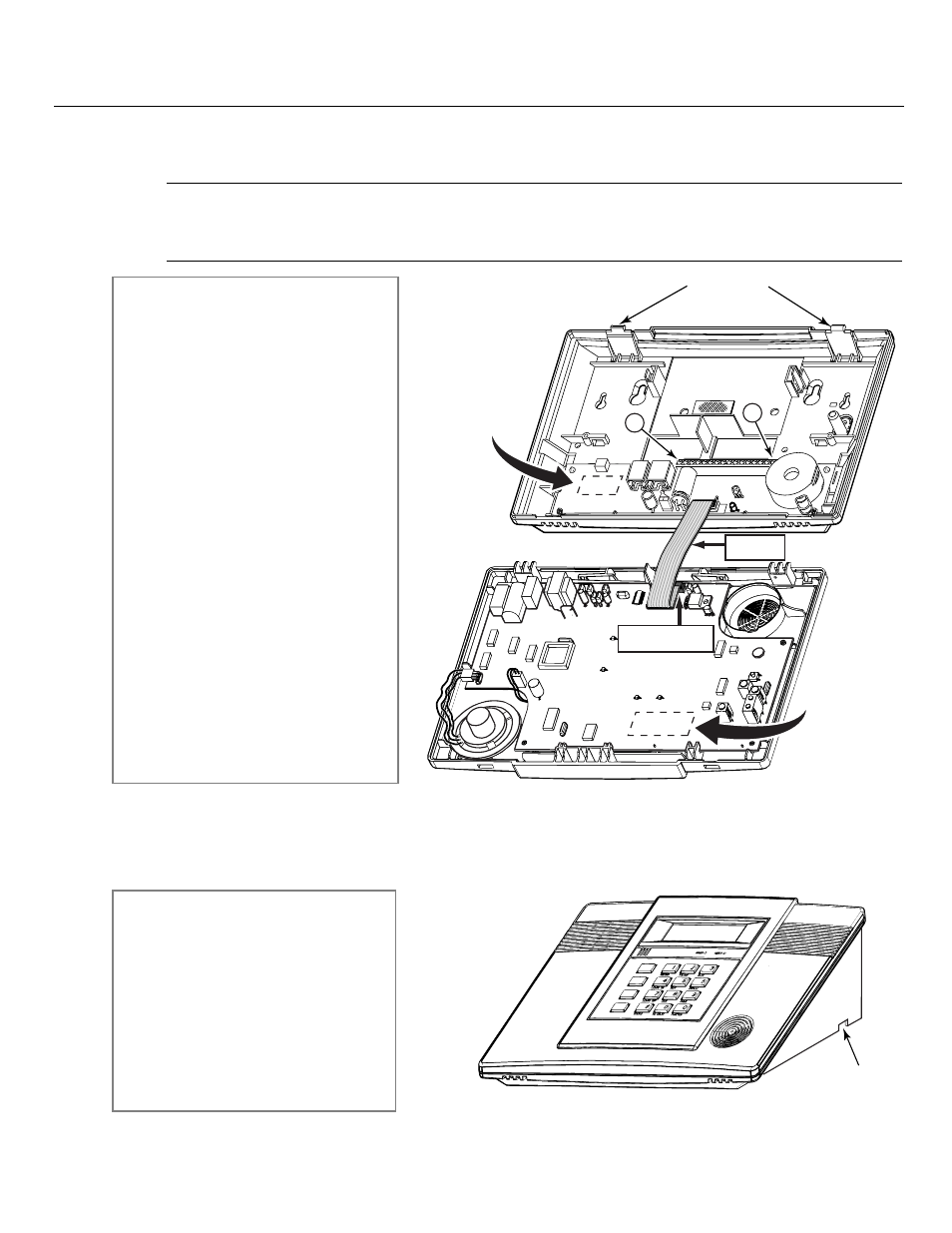
The illustration below shows the front assembly separated from the back plate.
!
DO NOT disconnect the ribbon cable from the terminal strip board. Disconnect the cable only from the
front assembly board.
Certain features differ between the LYNXR/LYNXR24 and the LYNXR-EN models. Verify the specific model
being installed prior to programming the system.
DISCONNECT
THIS END ONLY!
01009-003-V0
MXXXX K5108
RED WIRE
MARKING
16
1
LOCKING TABS
PC BOARD
PART NUMBER
LOCATION
PC BOARD
PART NUMBER
LOCATION
Desktop Mounting
If desired, an optional mounting base (model LYNX-DM, purchased separately) allows the LYNXR-Series controls to be
used on a desktop.
ADD
ESCAPE
DELETE
SELECT
AWAY
OFF
STAY
AUX
01009-004-V1
WIRE ENTRY
KNOCKOUT
(1 of 3)
1. Separate the front assembly from the
back plate by pressing on the two
locking tabs at the top of the unit.
2. Carefully disconnect the ribbon cable
from the front assembly, leaving the
ribbon cable connected to the
terminal block PC board. The back
plate contains the terminal block for
making wiring connections.
3. Mount the back plate to a sturdy wall,
feeding the field wiring through the
appropriate openings in the back
plate.
4. After wiring connections are made,
carefully reconnect the ribbon cable to
the front assembly PC board
connector (properly aligning the red
wire).
5. Before closing the assembly, verify
which LYNXR model is being installed
by checking the model number printed
on the PC Boards. (Example:
SALYNXREN indicates the unit being
installed is a LYNXR-EN.)
6. Snap the front assembly to the back
plate so it is secured by the locking
tabs.
1. Slide the control panel onto the
mounting base locking tabs
.
2. Bring all wiring through the bottom of
the mounting base, using one of the
three wire entry locations, before
making connections to the control
panel.
3. Use tie-wraps to secure the wiring to
the built-in wire loops as needed. Use
the two supplied screws to secure the
control panel to the mounting base.