Nomenclature, Features, Application – Heatcraft Refrigeration Products U User Manual
Page 5: High profile reach-in unit cooler, Model c
5
nomenclature
c (K) B G
Voltage
a = 115/1/60
B = 08-0/1/60
high Profile Unit cooler
size
Bohn-Kote® coil
(optional)
Vintage
Features
• Textured aluminum cabinet
• Molded Lexan® guard
• Drain fitting at 45-degree angle so drain can be run
through bottom or back of refrigerator
• Aluminum hangers automatically space the unit to the
correct distance from the back wall
• Stainless steel screws - prevent rust streaks
• Room for expansion valve inside the unit
• Knockouts in sides and top plus openings in rear provide
maximum flexibility for electrical connection
• Full collar aluminum fins on expanded copper tubes
• Internal junction box with pigtail leads for
electrical connection
• Motors are thermally protected and
permanently lubricated
• All models UL listed for US and Canada
• UL classified to NSF standards
• Optional Bohn-Kote® coated coil available (Model CK)
for optimum protection in corrosive environments
Sweat inlet connection to reduce leaks
(flare connection available as a ship loose option)
application
Model c
is the ideal unit for refrigerated reach-ins. It mounts
to the top of the refrigerator and discharges cold air against the
back wall. With this air flow pattern, the air is not blasted on
the product but is diffused along the back wall and then gently
drawn across the product as it returns to the unit. Thus uniform
temperatures are maintained throughout the refrigerator. In
addition, door sweating and refrigeration loss due to door
opening is greatly reduced because the air is not discharged
against the doors.
Model c
high Profile Reach-In Unit cooler
†
Model 43 uses external equalized expansion valve
table 5. Performance and electrical Data
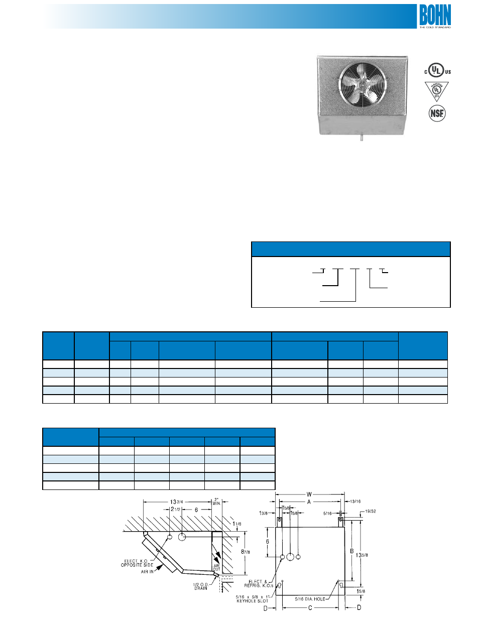
Diagram . Dimensions
table 6. Physical Data
Model
BtUh
10°F tD
Motor Data
connections (in.)
approx.
ship Wt.
(lbs.)
cFM
Qty.
115/1/60
total Fla
08-0/1/60
total Fla
coil Inlet
oD
suction
ID
Drain
oD
C13
1,300
235
1
1.0
0.5
3/8
3/8
1/2
16
C17
1,700
250
1
1.0
0.5
3/8
1/2
1/2
17
C23
2,300
265
1
1.0
0.5
3/8
1/2
1/2
22
C30
3,000
480
2
2.0
1.0
3/8
1/2
1/2
27
C43
†
4,300
520
2
2.0
1.0
1/2
1/2
1/2
40
Model
Dimensions (in.)
a
B
c
D
W
C13
12-5/8
12-3/8
11-7/16
1-3/8
14-1/4
C17
15-5/8
12-3/8
14-7/16
1-3/8
17-1/4
C23
21-1/8
12-3/8
21-1/16
7/8
22-3/4
C30
26-1/8
12-3/8
25-13/16
1
27-3/4
C43
36-5/16
-
-
-
38