5700 act wood stove, Door handle assembly, Baffle removal and installation – Hearth and Home Technologies 820-0721 User Manual
Page 24
5700 ACT Wood Stove
Page 24
September 1, 2008
R
250-7090e
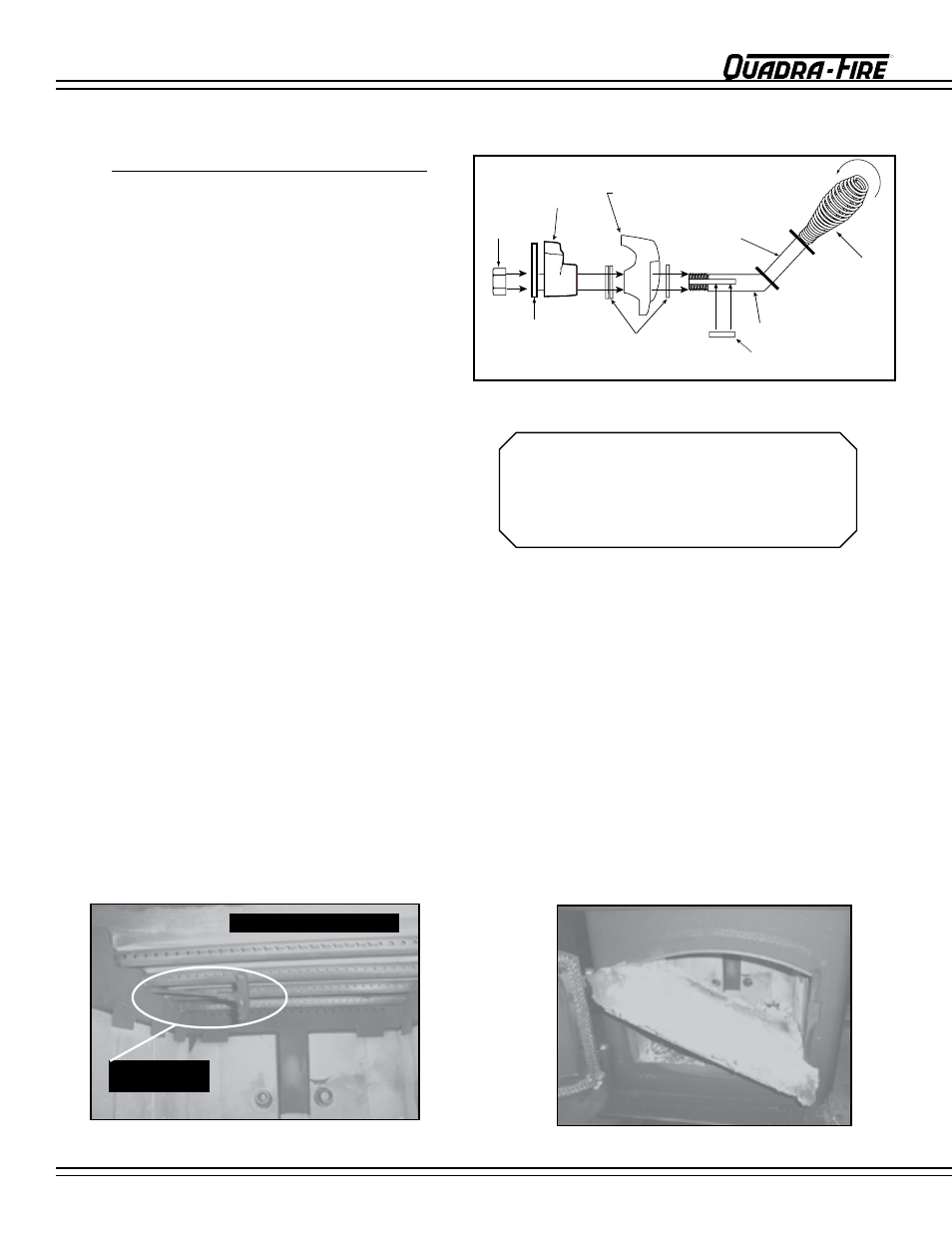
FIGURE 24C - Baffle with ceramic blanket on top.
Allen wrench
on retainer bolt
First tube has larger holes
FIGURE 24B - Allen wrench on retainer bolt.
DOOR HANDLE ASSEMBLY
1. remove all ash from the firebox, and extinguish all hot embers before disposal into a metal container.
2. With a 3/16” allen wrench, remove the 2 front secondary combustion tube retainer bolts on the secondary air channel under the
end of the front tubes.
See Figure 24B. NOTe: Soak the bolts with penetrating oil for at least 15 minutes before trying to remove
them.
3. To remove the secondary combustion tubes, slide the tube to one side until one end is out of its hole. Then, while lifting that end
of the baffle, pull the tube up over the secondary air channel and out of the hole at the other end.
NOTE: When replacing the secondary tubes, be sure the tube with the larger holes is placed in the front or your stove will not
operate properly.
4. Slide baffle and ceramic blanket forward to front of stove, tilt down and slide to the door. Tilt to one side and slide both through
door at the same time. Keep them tilted as you lift it out of the door.
See Figure 24C.
5. To install the baffle and ceramic blanket, repeat steps 2 through 4 in reverse. be sure that the fiber board baffle is pushed back
fully and the blanket is down flat. The front of the blanket should be flush with the front of the baffle.
BAFFLE REMOVAL AND INSTALLATION
1. Install washer on door handle shaft.
2. Slide door handle through door.
3. Install second washer(s) as shown.
4. Install key in groove.
5. Align groove in latch cam with key; slide latch cam over
shaft.
6. Install secondary latch included in the Component Pack
inside the firebox.
7. Install locknut.
CAUTION! DO NOT OVERTIGHTEN LOCkNUT. DOOR
HANDLE NEEDS TO MOVE SMOOTHLY.
8. Install spring handle turning in a counter-clockwise motion
on handle leaving a 3” (76mm) clearance from bend in
door handle rod to end of spring handle.
See Figure
24.
SPRING HANDLE WARNING!
3” (76mm) clearance is required from bend in
Door Handle Rod to end of the Spring Handle.
If installed within that 3” (76mm) area, Spring
Handle will get hot and may cause injury.
NOTE: SEE PAGE 18 FOR OPERATING INSTRUCTIONS
FIGURE 24A
Locknut
Door Cross Section
(example)
Latch Cam
Spacing
Washers
Square Key
Door Handle
Spring
Handle
3" (76mm) clearance
required from bend in Door
Handle Rod to end of Spring
Handle.
Secondary
Latch