Operating the mower, 36 cutterhead position control, Dual lift configuration control – Hayter Mowers T424 User Manual
Page 36
953910KG141004
OPERATING THE MOWER
1.36
1.36
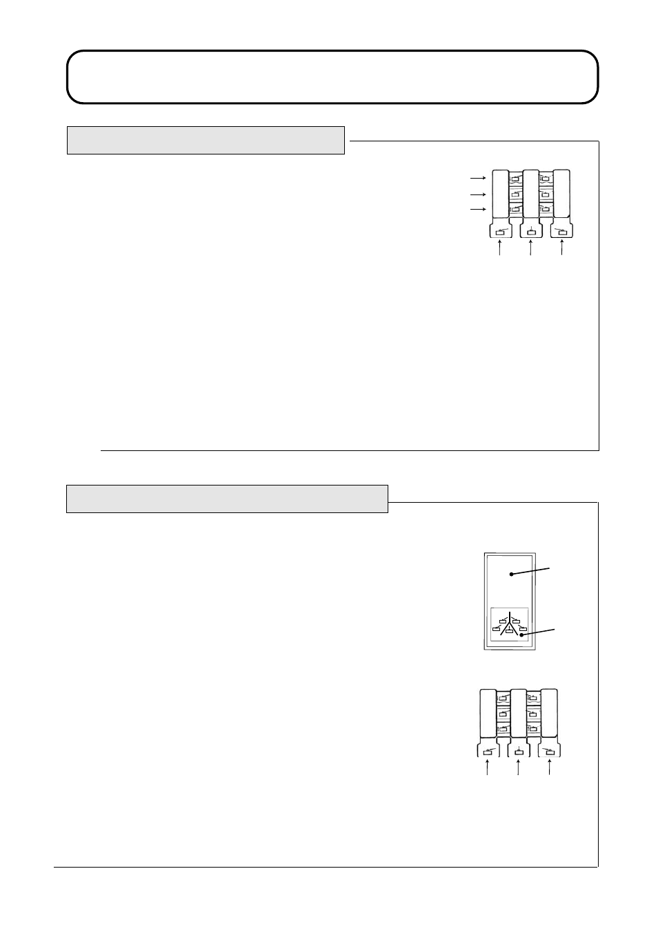
CUTTERHEAD POSITION CONTROL
The cutterheads may be raised or lowered using the bank of 3 lift control
levers.
To lower the cutterheads, operate the lift control levers in a downward
direction until locked in position 1. If the cutterhead drive switch is in the
‘ON’ position, the cylinder drive will engage when the cutterheads are
approximately 300mm above ground level.
IMPORTANT: PREVENT DAMAGE - The lift control levers must be
locked in position 1 while mowing. NEVER mow with the lift control
levers in position 2 (neutral).
To raise the cutterheads, operate the lift control levers in an upward direction
and hold in position 3. If the cutterhead drive switch is in the ‘ON’ position,
the cylinder drive will disengage when the cutterheads are approximately
300mm above ground level. Release the lift control levers when the
cutterheads are at the required height. The control levers will automatically
return to position 2 (neutral).
1. Down / float
2. Neutral
3. Raise
4. LH Wing or LH Wing+LH Front*
5. Centre+LH/RH Front or Centre*
6. RH Wing or RH Wing+RH Front*
*Depending on which lift configuration
is selected. Refer-Dual Lift Configuration
Control.
4A953B03A
1
2
3
4
5
6
DUAL LIFT CONFIGURATION CONTROL
The dual lift configuration control function enables the lift controls to be
used in two ways as follows:
Five gang mode, lift configuration (1):
Control switch in position 1
LH lift lever (3) controls LH wing cutterhead
Centre lift lever (4) controls LH front + centre + RH front cutterheads
RH lift lever (5) controls RH wing cutterhead
Three/five gang mode, lift configuration (2):
Control switch in position 2
LH lift lever (3) controls LH wing + LH front cutterheads
Centre lift lever (4) controls centre cutterhead
RH lift lever (5) controls RH wing + RH front cutterheads
With the LH and RH wing cutterheads locked in the fully raised
transport position.
Control switch in position 2
LH lift lever (3) controls LH front cutterhead
Centre lift lever (4) controls centre cutterhead
RH lift lever (5) controls RH front cutterhead
3D95301
1
2
4A953B03B
3
4
5
1. 5 Gang Mode
2. 3/5 Gang Mode
3. LH Lift Lever
4. Centre Lift Lever
5. RH Lift Lever