Operating the mower, Identification of controls – Hayter Mowers T424 User Manual
Page 26
953910KG141004
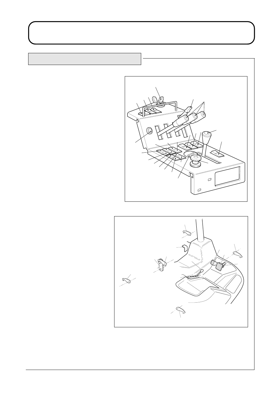
OPERATING THE MOWER
1.26
1.26
1. Parking brake lever.
2. Lighting switch
(supplied with lighting kit).
3. Warning beacon switch
(supplied with beacon kit).
4. Hazard warning switch
(supplied with lighting kit).
5. Cutterhead position controls.
6. Throttle control lever.
7. Ignition key.
8. Cutterhead drive switch.
9. Dip beam / main beam light switch
(supplied with lighting kit).
10. Direction indicator switch
(supplied with lighting kit).
11. Horn button.
12. Transmission oil filter indicator.
13. Oil pressure indicator.
14. Transmission temperature indicator.
15. Return oil filter indicator.
16. Battery warning indicator.
17. Engine temperature warning indicator.
18. Glow plug indicator.
19. Cutterhead drive off indicator.
20. Parking brake indicator.
21. Transmission neutral indicator.
22. Weight transfer control.
23. ‘Work/Transport’ mode switch.
24. Centre cutterhead transport latch.
25. LH front cutterhead transport latch.
26. RH front cutterhead transport latch.
27. Centre cutterhead transport latch.
28. LH wing unit transport latch.
29. RH wing unit transport latch.
30. Differential lock pedal.
31.Dual lift configuration switch.
32. Wash / wipe switch
(supplied with cab kit).
33. Forward travel pedal.
34. Reverse travel pedal
35. Forward travel speed backstop lever.
36. Forward travel speed backstop cam.
37. Hour Meter
4A953B01A
1
2
5
6
10
9
4
7
8
11
14
13
12
15
16
18
19
20
21
17
22
3
23
37
HOURS
QUARTZ
CURTIS
1
10
1D953S01A
24
27
25
29
28
26
33
30
36
34
35
IDENTIFICATION OF CONTROLS