C. vent termination – Heat & Glo Fireplace Heat-n- Glo BE-41 User Manual
Page 21
21
!
C. Vent Termination
For Horizontal Terminations - To attach and secure the
termination to the last section of horizontal vent:
Rotate and interlock the ends as described at the begin-
ning of the Installing Vent Components section.
The termination kit should pass through the wall firestops
from the exterior of the building.
Adjust the termination cap to its final exterior position on
the building.
Figure 24. Round & Trapezoid Termination Caps
!
WARNING: THE BOTTOM OF THE VENT
TERMINATION CAP MUST BE A MINIMUM
OF 12 INCHES (305 MM) ABOVE GROUND LEVEL
(GRADE). THE TOP OF THE CAP MUST BE A MIN-
IMUM OF 18 INCHES (457 MM) BELOW COMBUS-
TIBLE MATERIAL, SUCH AS A DECK. THE SIDE
OF THE CAP MUST BE A MINIMUM OF 6 INCHES
(152 MM) AWAY FROM A PARALLEL OUTSIDE
WALL. VENTING TERMINALS SHALL NOT BE RE-
CESSED INTO A WALL OR SIDING. SEE THE FOL-
LOWING DIAGRAM FOR VENT TERMINATION
CLEARANCES.
ROUND CAP TERMINATION
PERFORATION CANNOT BE
INSIDE THE WALL
7 1/2"
(191mm)
MINIMUM
TRAPEZOID CAP TERMINATION
7 1/4"
(184mm)
WARNING: THE TERMINATION CAP MUST BE PO-
SITIONED SO THAT THE ARROW IS POINTING UP.
For roundcap termination kits:
Use the exterior pipelock hole on the round flange of the
wall firestop to secure the vent pipe in place.
For trapezoidal cap termination kits:
Using screws secure the cap to the exterior wall through
the flanges in the cap.
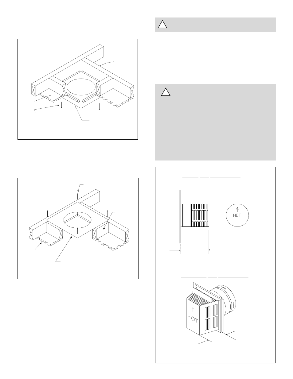
Figure 22. Ceiling Firestop (Ceiling Side)
If the area above the ceiling is NOT an attic, position and
secure the ceiling firestop on the ceiling side of the previously
cut and framed hole.
If the area above the ceiling IS an attic, position and secure
the firestop on top of the previously framed hole.
NOTE: Keep insulation away from the vent pipe at least
1 inch (25mm).
Figure 23. Attic Firestop
JOIST
CEILING FIRESTOP
CEILING
NAILS (4 REQUIRED)
CEILING
CEILING FIRESTOP
RAFTER
NAILS (4 REQUIRED)