Caution, Wiring – Honeywell CHRONOTERM IV T8624D User Manual
Page 2
69-1074
2
T8624D CHRONOTHERM
®
IV DELUXE ZONE MULTISTAGE THERMOSTAT
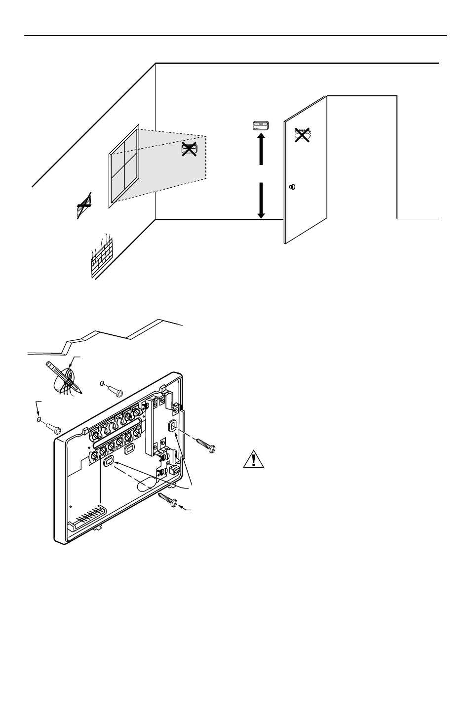
5 FEET
[1.5 METERS]
YES
NO
NO
NO
M10106
Fig. 1. Typical location of thermostat.
Fig. 2. Mounting the wallplate.
·
Use a pencil to mark the mounting holes. See Fig. 2.
»
Remove the wallplate from the wall and drill two
3/16 inch holes in the wall (if drywall) as marked.
For firmer material such as plaster, drill two
7/32 inch holes. Gently tap anchors (provided) into
the drilled holes until flush with the wall.
¿
Position the wallplate over the holes, pulling wires
through the wiring opening.
´
Loosely insert the mounting screws into the holes.
²
Tighten mounting screws.
WIRING
All wiring must comply with local electrical codes and
ordinances. Refer to Fig. 3 and 4 for typical hookups. A
letter code is located near each terminal for identification.
CAUTION
Disconnect power before wiring to prevent
electrical shock or equipment damage.
³
Loosen the terminal screws on the wallplate and
connect the system wires. See Fig. 5.
IMPORTANT
Use 18 gauge, color-coded thermostat cable for
proper wiring.
·
Securely tighten each terminal screw.
»
Push excess wire back into the hole.
¿
Plug the hole with nonflammable insulation to
prevent drafts from affecting the thermostat.
WIRES
THROUGH WALL
WALL
MOUNTING
HOLES
M15044
MOUNTING
SCREWS
WALL
ANCHORS
(2)