Rear panel connections – Harman-Kardon AVR 745 User Manual
Page 7
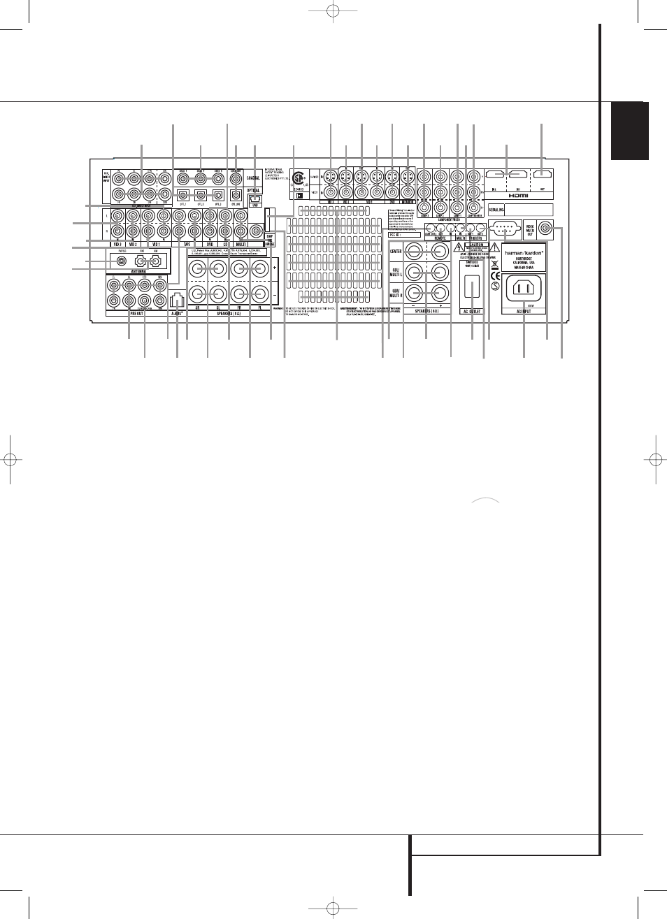
REAR PANEL CONNECTIONS
7
ENGLISH
Rear Panel Connections
MODEL NO. AVR 745
SUB 2
b
Z
Y
X
a
0
1
4
3
8
2
F
6
D
7
h
d
l
k
I
G
j
c
N
M
E
e
g
K
W
J
L
f
O
C
B
P
Q
S
T
R
i
H
5
A
U
V
9
230 V/60Hz
230 V/60Hz
0
1
2
3
4
5
6
7
8
9
A
B
C
D
E
F
G
H
I
J
K
L
M
N
O
P
Q
R
S
T
U
V
W
X
Y
Z
a
b
c
d
e
f
g
h
i
j
k
l
AM Antenna
FM Antenna
Tape Inputs
Tape Outputs
Main Subwoofer Output
DVD Audio Inputs
CD Inputs
Multiroom Audio Outputs
A-BUS Connector
8-Channel Direct Inputs
Digital Audio Outputs
Video Monitor Outputs
DVD Video Inputs
Front Speaker Outputs
Center Speaker Outputs
Surround Speaker Outputs
Switched AC Accessory Outlet
USB Connector
AC Power Cord Jack
Video 2 Component Video Inputs
Component Video Outputs
Video 1 Component Video Inputs
Remote IR Output
Remote IR Input
Multiroom IR Input
Video 1 Video Outputs
Video 1 Video Inputs
HDMI Output
Video 3 Video Inputs
Video 2 Video Inputs
Optical Digital Inputs
Coaxial Digital Inputs
HDMI Inputs
Video 2 Audio Inputs
Video 3 Audio Inputs
Video 1 Audio Inputs
Video 1 Audio Outputs
Preamp Outputs
Surround Back/Multiroom Speaker Outputs
RS-232 Port
Fan Vents
DVD/Video 3 Component Video Inputs
Remote IR Carrier Output
Subwoofer 2 Output
The Bridge
Digital Media Player
(DMP) Input
Trigger 1 Output
Trigger 2 Output
Multiroom Video Output
The
Bridge
TM
NOTE: To assist in making the correct connec-
tions for multichannel input/output and speaker
connections, all connection jacks and terminals
have been color coded in conformance with the
latest CEA standards as follows:
Front Left:
White
Front Right:
Red
Center:
Green
Surround Left:
Blue
Surround Right:
Gray
Surround Back Left:
Brown
Surround Back Right:
Tan
Subwoofer (LFE):
Purple
Digital Audio:
Orange
Composite Video:
Yellow
Component Video “Y”:
Green
Component Video “Pr”:
Red
Component Video “Pb”: Blue
0 AM Antenna: Connect the AM loop antenna
supplied with the receiver to these terminals. If an
external AM antenna is used, make connections to
the AM and GND terminals in accordance with
the instructions supplied with the antenna.
1 FM Antenna: Connect the supplied indoor or
an optional external FM antenna to this terminal.
2 Tape Inputs: Connect these jacks to the
PLAY/OUT jacks of an audio recorder.
3 Tape Outputs: Connect these jacks to the
RECORD/INPUT jacks of an audio recorder.
4 Main Subwoofer Output: Connect this
jack to the line-level input of a powered sub-
woofer. If an external subwoofer amplifier is
used, connect this jack to the subwoofer
amplifier input. If only one subwoofer is used in
your system, connect it here.
5 DVD Audio Inputs: Connect these jacks to
the analog audio jacks on a DVD or other audio
or video source.
6 CD Inputs: Connect these jacks to the
analog output of a compact disc player or CD
changer or any other audio source.
7 Multiroom Audio Outputs: Connect these
jacks to an optional audio power amplifier to lis-
ten to the source selected by the multiroom sys-
tem in a remote room.
8 A-BUS Connector: Connect this jack to an
optional A-BUS-certified remote room keypad or
amplifier to extend the multiroom capabilities of
your AVR. See page 18 for more information on
A-BUS.
29510_AVR745_Engelsk 30/10/06 9:31 Side 7