Parallel interface, Input connector, Signal descriptions – Epson 420i User Manual
Page 24
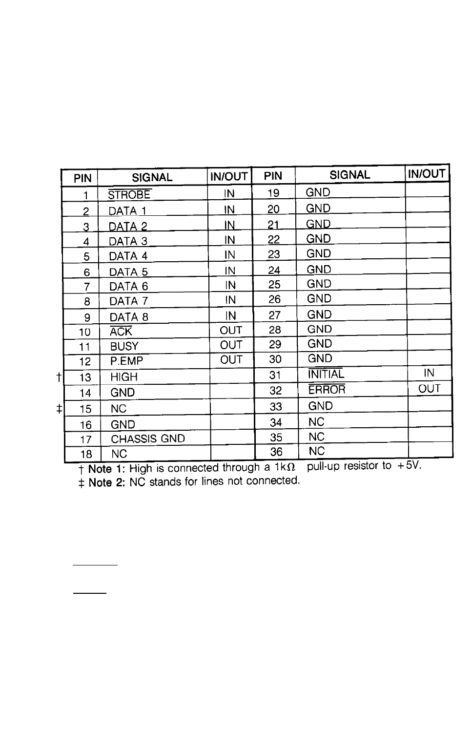
PARALLEL INTERFACE
Input Connector
Cable side connector
Printer side connector
Signal Diagram
DDK 36 pin 57-30360-D8 or equivalent
DDK 36 pin 57-40360-12 or equivalent
Signal Descriptions
1. Input Signals to the Printer.
* DATA 1-DATA 8
8-bit data signal, with “1” being HIGH.
* STROBE
Strobe signal used to read 8 bits of data. Data is input when the signal is LOW.
* INITIAL
Puts the printer into its initial state. This signal is usually HIGH. When it goes
LOW and then HIGH again, the printer is initialized.
2. Signals from the Printer
* BUSY
This signal shows that the printer is in the BUSY state. When it is HIGH, data
cannot be received. The following are conditions for which a HIGH BUSY signal
is output:
18
See also other documents in the category Epson Printers:
- Stylus Pro 7800 (11 pages)
- Stylus Pro 4000 (49 pages)
- Stylus Photo R300 (2 pages)
- Stylus Pro 7000 (147 pages)
- AcuLaser C3000 (316 pages)
- Stylus Pro 7900 (24 pages)
- Stylus Pro 4450 (21 pages)
- 1000 (272 pages)
- T034120 (4 pages)
- T580300 (4 pages)
- 300 (91 pages)
- B 510DN (190 pages)
- B 510DN (218 pages)
- Stylus NX510 (8 pages)
- Stylus Photo RX580 (95 pages)
- T549300 (4 pages)
- B 500DN (168 pages)
- AculaserCX11NF (5 pages)
- 480SXU (24 pages)
- 4500 (317 pages)
- STYLUS RX500 (99 pages)
- 2100 (13 pages)
- Stylus NX215 (2 pages)
- T098320 (4 pages)
- T041020 (4 pages)
- R210 (8 pages)
- All-In-One Stylus Photo RX600 (164 pages)
- 777I (53 pages)
- T033120 (4 pages)
- Stylus CX7000F (8 pages)
- 60 (113 pages)
- T034220 (4 pages)
- WorkForce 40 Series (36 pages)
- T054220 (4 pages)
- Stylus CX3200 (11 pages)
- Stylus CX7800 (18 pages)
- T060220 (4 pages)
- 2500 (180 pages)
- AcuLaser CX11N (32 pages)
- AcuLaser CX11N (4 pages)
- 2000P (16 pages)
- T606600 (4 pages)
- Stylus CX6000 (18 pages)
- FS-4000DN (2 pages)
- MSDS T544700 (4 pages)