Figure 7 – Emerson 3000 User Manual
Page 19
Installation (Applicable to all Models)
13
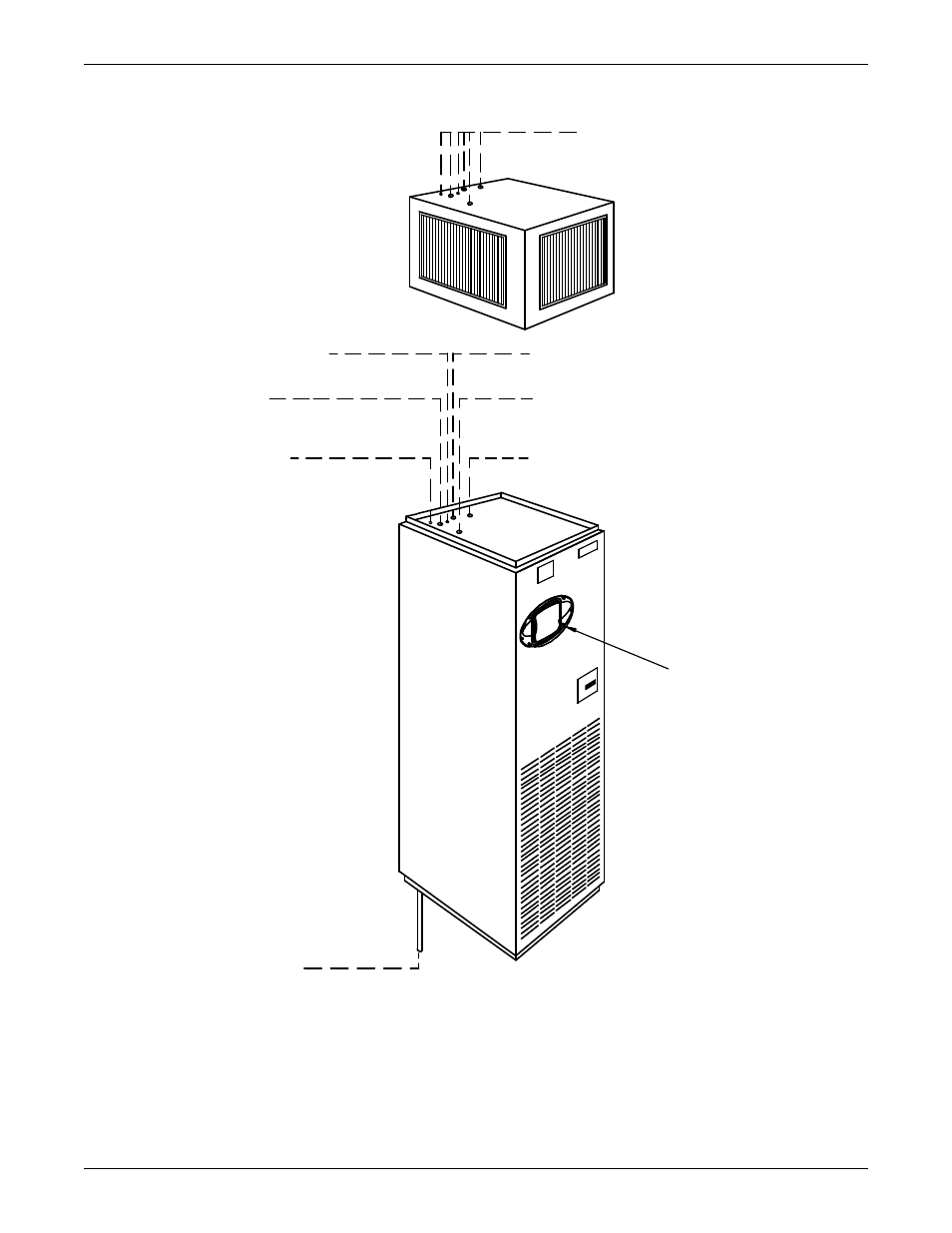
Figure 7
Piping connections for split system fan coil units - Upflow models
DPN000375
Rev. 01
Piping outlet locations through the
plenum are the same as the unit.
See below for descriptions and
connection sizes.
Humidifier Water Supply Line
1/4" OD CU
Suction Refrigerant Line
#11 Quick Connect on Models BU036E/BU035E
1 1/8" OD CU on Models BU060E/BU059E
Condensate Pump Line
1/2" OD CU; used only
if optional condensate pump is ordered.
Hot Water Return
5/8" OD CU (optional)
Liquid Refrigerant Line
#6 Quick Connect on Models BU036E/BU035E
1/2" OD CU on Models BU060E/BU059E
Hot Water Supply
5/8" OD CU (optional)
iCOM Control
Panel
Condensate Drain; 3/4" FPT
Field-pitch a min. of 1/8" (3.2mm) per ft. (305mm). Units without
a condensate pump have a factory-supplied trap in the unit, so a
field trap should not be added. Units with a condensate pump will
require a field-supplied trap downstream from the pump. The
drain line must comply with all applicable codes. (If condensate
pump is ordered, piping is out top of unit).
PIPING OUTLET LOCATIONS
(See Cabinet and Floor Planning
Dimensional Data for Piping
Opening Sizes.)