GE 600 Series 30 Inch Slide-In Gas Smart Range Installation Instructions User Manual
Page 4
INSTALLATION INSTRUCTION
31-2001195 Rev. 1 09-23 GEA
10
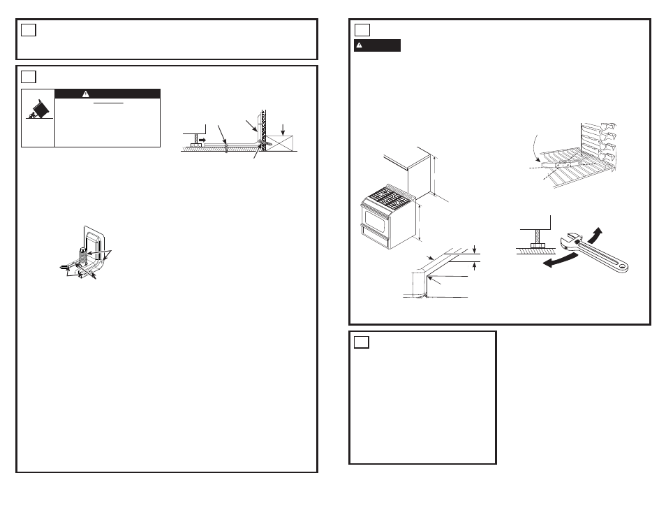
LEVEL THE RANGE
WARNING
Never completely remove the
leveling leg as the range will not be secured to
the anti-tip device properly.
A. Plug in the unit and remove the drawer.
Refer to your owner’s manual for
instructions.
B. Measure the height of your countertop at the
rear of the opening (X).
C. Adjust two rear leveling legs so that the rear
of cooktop is higher than or equal to the
counter (Y).
D. Slide unit into place taking care to engage
the leveling legs in the anti-tip device.
E. Look under the unit and verify that the rear
leg is fully engaged with the anti-tip device.
If not, remove the unit and adjust the height
of the rear leg so that it is properly engaged.
F. Install racks in the oven.
G. Check for levelness by placing a spirit
level on one of the oven shelves. Take two
readings—with the level placed diagonally
first in one direction and then the other.
H. Use an adjustable wrench to adjust the front
leveling legs until the range is level.
I. Position cord so that it does not interfere
with drawer.
J. Reinstall the drawer. Refer to your owner’s
manual for instructions.
X
Y
Cooktop
0" or Greater
Counter
Spirit level
9
ANTI-TIP DEVICE INSTALLATION
To reduce the risk of tipping the range, the
range must be secured by a properly installed
anti-tip bracket. Remove any currently used
anti-tip bracket and install with the provided
anti-tip bracket.
1.
IMPORTANT
: Determine the final location
of the range before attempting to install the
bracket. Remove existing anti-tip bracket
from install space, if present.
a. Place the bracket on the floor with the
back edge against the rear wall. If the
range does not reach the rear wall, align
the back edge of the bracket with the rear
panel of the range in its final location.
If bracket does not touch the rear wall,
you MUST screw bracket to FLOOR as
described in Step 2.
b. Position the side of the bracket against
either the left or right cabinet. If there is
no adjacent cabinet, align the edge of
the bracket with the side panel of the
range in its final location. If the countertop
overhangs The cabinet, offset the bracket
from the cabinet by the amount of
overhang.
c. Mark the location for the pair of holes to be
used (see illustration above).
NOTE
: For FLOOR installation use either
Loc A or B. For REAR WALL installation
use Loc C.
2. The bracket must be screwed to either the
FLOOR or REAR WALL.
FLOOR Installation:
WOOD FLOOR:
Use the screws provided to
secure the bracket using the pair of marked
holes (either Loc A or B).
CONCRETE FLOOR:
Using a concrete
ELWGULOOD´SLORWKROH´GHHSLQWRWKH
concrete at the center of each of the marked
holes (either Loc A or B). Use the screws
provided to secure the bracket into the floor.
REAR WALL Installation
:
Use the 2 screws provided to secure the
bracket using the pair of marked holes at
Loc C. The screws MUST enter into a wood
sill plate. If the wall contains any metal studs
or similar materials, then the floor must be
used.
3. To check if the bracket is installed and
engaged properly, look underneath the
range to see that the rear leveling leg is
engaged in the bracket. On some models,
the storage drawer or kick panel can be
removed for easy inspection. If visual
inspection is not possible, slide the range
forward, confirm the anti-tip bracket is
securely attached to the floor or wall, and
slide the range back so the rear leveling
leg is under the anti-tip bracket. If your
range is removed for cleaning, servicing,
or any reason, be sure the anti-tip device
is reengaged properly when the range is
replaced. Failure to take this precaution
could result in tipping of the range and can
result in death or serious burns to children
or adults. Never completely remove the
leveling legs or the range will not be secured
to the anti-tip device properly.
Anti-Tip
Bracket Kit
Included
Loc A
Loc B
Loc C
Two screws must enter floor
at Loc A or B or wall at Loc C.
Rear Wall
Screw must enter
wood or concrete
Attachment to Floor or Rear Wall
Wall Sill Plate
Screw must enter wood
Bracket
8
CHECK BAKE AND BROIL BURNERS
Ŷ6HW%DNHIXQFWLRQWR)%XUQHUVKRXOG
light in 30 to 60 seconds.
Ŷ6HWEURLOWR%URLO+L0RGHOVZLWKDJDV
burner should light in 30 to 60 seconds.
11
FINAL INSTALLATION
CHECKLIST
Ŷ0DNHVXUHWKHIORZRIFRPEXVWLRQDQG
ventilation air to the range is unobstructed.
Ŷ&KHFNWKDWDOOSDFNLQJPDWHULDOVDQGWDSH
have been removed. This will include
tape on metal panel under control knobs
(if applicable), adhesive tape, wire ties,
cardboard and protective plastic. Failure
to remove these materials could result
in damage to the appliance once the
appliance has been turned on and surfaces
have heated.
Ŷ0DNHVXUHDOOFRQWUROVDUHOHIWLQWKHRII
position.
Raise
Range
Lower
Range
• A child or adult can tip the range and be killed.
• Install the anti-tip bracket provided with the unit
to the wall or floor.
• Engage the range to the anti-tip bracket by sliding the
range back such that the foot is engaged.
• Re-engage the anti-tip bracket if the range is moved.
• Failure to do so can result in death or serious burns
to children or adults.
Tip-Over Hazard
WARNING