Dimensions and clearances, Installation at high altitude, Mobile home - additional installation requirements – GE 600 Series 30 Inch Slide-In Gas Smart Range Installation Instructions User Manual
Page 2: Remove packaging materials, Attach required filler trim, Gas supply
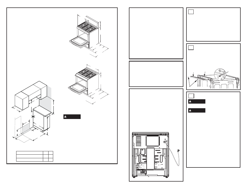
DIMENSIONS AND CLEARANCES
Provide adequate clearances between the
range and adjacent combustible surfaces.
These dimensions must be met for safe use of
your range.
$OORZ´FPPLQLPXPFOHDUDQFH
between burners and bottom of unprotected
ZRRGRUPHWDOFDELQHWRUDOORZD´
cm) minimum when bottom of wood or metal
FDELQHWLVSURWHFWHGE\QROHVVWKDQ´
mm) thick flame-retardant millboard covered
with no less than No. 28 MSG sheet metal
´>PP@WKLFN´
PPWKLFNVWDLQOHVVVWHHO´PP
DOXPLQXPRU´PPFRSSHU
Installation of a listed microwave oven or
cooking appliance over the cooktop shall
conform to the installation instructions packed
with that appliance.
)RULVODQGLQVWDOODWLRQPDLQWDLQ´PLQLPXP
from cutout to back edge of countertop and
´PLQLPXPIURPFXWRXWWRVLGHHGJHVRI
countertop.
Gas Pipe and Electrical Outlet Locations
CAUTION
To prevent drafts from
affecting burner operation, seal all openings
in floor under appliance and behind appliance
wall.
Before installing your range on linoleum or
any other synthetic floor covering, make sure
the floor covering can withstand 180°F without
shrinking, warping or discoloring. Do not install
the range over carpeting unless a sheet of
´WKLFNSO\ZRRGRUVLPLODULQVXODWRULVSODFHG
between the range and carpeting.
´
Minimum
to cabinets
below
cooktop
´VHH
note)
´
´
´
max to
cabinets
above
counter
B
Right
side
A
Left side
Minimum
to side wall
´
´
3 1/4
´
´
´
´
´
Side
Wall
Gas
and
electrical
supply
Gas Range dimensions
A
B
4 Cooktop Burners
´
´
5 Cooktop Burners
´
´
NOTE:
Minimum to bare cabinet
above: see Installation Instructions for
alternate installation configurations.
INSTALLATION AT HIGH
ALTITUDE
Over 6000ft, product configured for natural
gas or propane requires installation of
kit (WB28X47007 for natural gas and
JXBUFS04 for propane gas). Follow the
instructions included with the kit.
MOBILE HOME - ADDITIONAL
INSTALLATION REQUIREMENTS
The installation of this range must conform
to the Manufactured Home Construction
and Safety Standard, Title 24 CFR, Part
3280 (formerly the Federal Standard for
Mobile Home Construction and Saftey, Title
24, HUD Part 280). When such standard
is not applicable, use the Standard for
Manufactured Home Installations, ANSI
A225.1/NFPA 501A or with local codes.
When this range is installed in a mobile
home, it must be secured to the floor during
transit. Any method of securing the range
is adequate as long as it conforms to the
standards listed above.
1
REMOVE PACKAGING
MATERIALS:
Failure to remove packaging materials
could result in damage to the appliance.
Remove all packing parts from oven, racks,
heating elements and drawer. Also, remove
protective film and labels on the outer door,
cooktop and control panel.
Consider recycling options for your appliance
packaging material.
2
ATTACH REQUIRED FILLER
TRIM
For ALL front control installations,
the
included filler trim must be installed. Remove
the two screws on rear trim indicated with
nearby arrows. Reuse these two screws to
attach the filler trim to the back of the range.
CONVERTING TO PROPANE GAS
(OR CONVERTING BACK TO
NATURAL GAS FROM PROPANE)
This range leaves the factory set for use
with natural gas. If you want to convert
to propane gas, the conversion must be
performed by a qualified propane gas
installer.
The conversion orifices and instructions can
be found in the owner’s manual packet.
Keep these instructions and all orifices in
case you want to convert back to natural gas.
Rear of Range
Pressure Regulator
3
GAS SUPPLY
WARNING
Fire Hazard: Do not use a
flame to check for gas leaks.
WARNING
Explosion Hazard: Do not
exceed 25 ft-lbs of torque when making
gas line connections. Overtightening may
crack the pressure regulator resulting in
fire or explosion hazard.
Gas Pressure Regulator
You must use the gas pressure regulator
supplied with this range. For proper
operations the inlet pressure to the regulator
should be as follows:
Natural Gas:
0LQLPXPSUHVVXUH´RI:DWHU&ROXPQ
0D[LPXPSUHVVXUH´RI:DWHU&ROXPQ
Propane Gas:
0LQLPXPSUHVVXUH´RI:DWHU&ROXPQ
0D[LPXPSUHVVXUH´RI:DWHU&ROXPQ
If you are not sure about the inlet pressure,
contact local gas supplier.
FRONT CONTROL
´
´
to
´
´
with handle
´
26
´
w/o handle
48
1/2"
Door Open
REAR CONTROL
´WR
36 1/2
´
´
with handle
´
´
w/o handle
47
1/2"
Door Open
Screws
Filler Trim
Rear Trim
Arrows on
both sides
Back of Range