GE 600 Series 30 Inch Slide-In Gas Smart Range Installation Instructions User Manual
Page 3
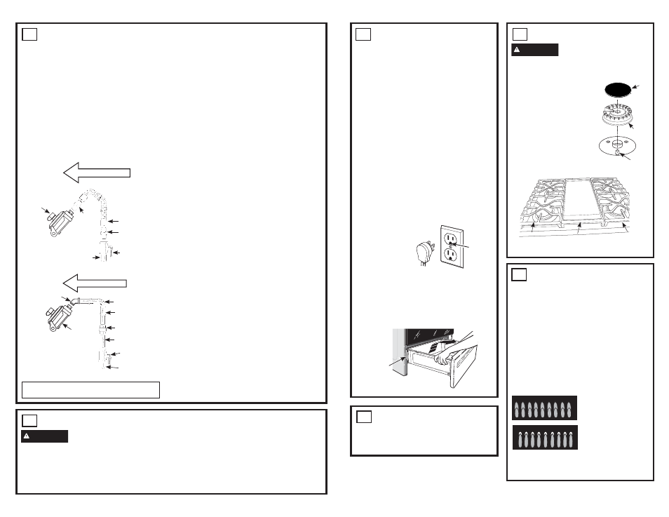
6
SURFACE BURNERS
WARNING
Fire or Explosion
Hazard:
Do not operate the burner without all
burner parts in place.
A.
Burners -
Place
surface burners into
corresponding positions
on cooktop.
B.
Caps -
Place caps on
proper size burner.
C.
Grates -
The left
and right grates are
interchangeable. Place
the grates on the cooktop.
3
GAS SUPPLY (Cont.)
Shut off the main gas supply valve before
disconnecting the old range and leave it off until
the new hook-up has been completed. Don’t
forget to relight the pilot on other gas appliances
when you turn the gas back on.
Because hard piping restricts movement of
the range, the use of a CSA International-
certified flexible metal appliance connector is
recommended unless local codes require a
hard-piped connection.
If the hard piping method is used, you must
carefully align the pipe; the range cannot be
moved after the connection is made.
CONNECTOR HOOKUP
To prevent gas leaks, put pipe joint compound
on, or wrap pipe thread tape with Teflon*
around, all male (external) pipe threads.
A. Install a manual shut-off valve in the gas line
in an easily accessed location outside of the
range. Make sure everyone operating the
range knows where and how to shut off the
gas supply to the range.
%,QVWDOOPDOH´IODUHXQLRQDGDSWHUWRWKH
´137LQWHUQDOWKUHDGDWLQOHWRIUHJXODWRU
Use a backup wrench on the regulator fitting
to avoid damage.
&,QVWDOOPDOH´RU´IODUHXQLRQDGDSWHU
to the NPT internal thread of the manual
shut-off valve, taking care to back-up the
shut-off valve to keep it from turning.
D. Connect flexible metal appliance connector to
the adapter on the range. Position range to
permit connection at the shut-off valve.
E. When all connections have been made, make
sure all range controls are in the off position
and turn on the main gas supply valve.
Use a liquid leak detector at all joints and
connections to check for leaks in the system.
When using pressures greater than 1/2 psig
to pressure test the gas supply system of the
residence, disconnect the range and individual
shut-off valve from the gas supply piping. When
using pressures of 1/2 psig or less to pressure
test the gas supply system, simply isolate the
range from the gas supply system by closing the
individual shut-off valve.
When checking for proper operation of the
UHJXODWRUWKHLQOHWSUHVVXUHPXVWEHDWOHDVW´
greater than the operating (manifold) pressure
as given on rating label of product.
*Teflon: Registered trademark of DuPont
4
ELECTRICAL CONNECTIONS
(Cont.)
Grounding
The power cord of this appliance is equipped
with a three-prong (grounding) plug which
plugs into a standard three-prong grounding
wall receptacle to minimize the possibility of
electric shock hazard from this appliance.
The customer should have the wall
receptacle and circuit checked by a qualified
electrician to make sure the receptacle is
properly grounded.
Where a standard two-prong wall
receptacle is encountered, it is the personal
responsibility and obligation of the customer
to have it replaced with a properly grounded
three-prong wall receptacle.
DO NOT, UNDER ANY CIRCUMSTANCES,
CUT OR REMOVE THE THIRD (GROUND)
PRONG FROM THE POWER CORD. DO
NOT USE AN ADAPTER. DO NOT USE AN
EXTENSION CORD
.
NOTE:
Ground
Fault Circuit
Interrupters
(GFCI’s) will not
affect performance
of the gas range
if operated on a GFCI-protected circuit but
occasional nuisance tripping of the GFCI
breaker is possible.
The rating plate is located on the frame
surrounding the drawer.
4
ELECTRICAL CONNECTIONS
WARNING
Shock Hazard:
This
appliance must be properly grounded. Failure to
do so can result in electric shock.
Electrical Requirements - 120-volt, 60 Hertz,
properly grounded circuit protected by a 15-amp
or 20-amp circuit breaker or time delay fuse. It
is recommended that a separate circuit serving
only this range be provided.
NOTE:
Use of automatic, wireless, or wired
external switches that shut off power to the
appliance are not recommended for this product.
Pressure
regulator
Gas Flow into Range
Flex
connector
(6 ft. max.)
Adapter
´RU´
Gas pipe
Adapter
Gas
shut-off
valve
Flexible
Option
Gas Flow into Range
Pressure
regulator
Elbow
Elbow
Nipple
Union
Nipple
Gas shut-off
valve
´RU´
Gas pipe
Rigid Pipe
Option
Installer: Inform the consumer of the
location of the gas shut-off valve.
Ensure
proper
ground
exists
before
use
Rating
plate
5
INSTALL KNOBS
Ŷ5HPRYHDOONQREVIURPSDFNDJLQJ
Ŷ ,QVWDOOWKHNQREVRQWRWKHFRRNWRSEXUQHU
shafts.
Electrode
Cap
Burner
Left
Grate
Right
Grate
Center
Grate or Griddle
(on some models)
7
CHECK SURFACE BURNERS
Push and turn a knob to the LITE position.
A clicking sound indicates proper operation
of the ignition system. When lighting any
burner, sparks will appear at all burners
but gas flows from only the one selected.
Once air is purged from the supply line,
burner should light within 4 seconds. After
burner lights, rotate the knob out of the LITE
position. Try each burner in succession until
all burners have been checked.
Quality of Flames
Determine the quality of flames visually.
Normal burner flames should look like (A)
or (B).
Normal flames may show signs of an orange
tint when well heated or signs of flickering
orange due to particles in the gas or air.
(A) Soft blue flames—
Normal for natural gas
(B) Yellow tips on
outer cones—
Normal for propane gas